9HUVD3XOVH3RZHU6XLWH6HULHV6HUYLFH0DQXDO 7+(25<2)23(5$7,21
5(9%
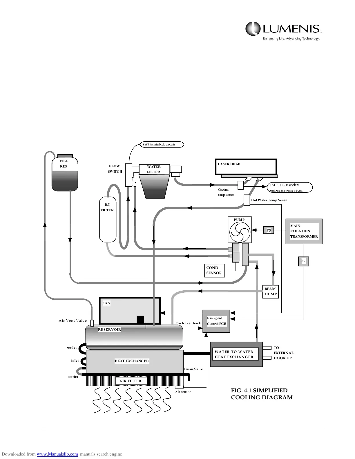
4.3 COOLING
Refer to the Coolant System Simplified Diagram (Fig 4.1). As the lamps in the laser head are flashed, heat
energy is produced in the flash lamps, rods, and housings. The cooling system transfers the heat energy from
the flash lamp, rod and housings to the outside air. It utilizes a closed loop, forced air heat exchanger which
contains approximately 2.5 gallons of distilled water. A speed controlled fan forces air through the heat
exchanger. The cooling system also provides cooling for the two beam dumps. Note that the system does not
contain an active chiller, therefore, the water can never be colder than ambient temperature during normal
operation.
)$1
+($7(;&+$1*(5
5(6(592,5
LQOHW
RXWOH W
RXWOH W
380 3
/$6(5+($'
:$7(5
),/7(5
',
),/7(5
)/2:
6:,7&+
6:WRLQW HUORFNFLUFXLWV
7R&383&%FRRODQW
W HPSHUDW XUHVHQVHFLUFXLW
)DQ6SHHG
&RQWURO3&%
0$,1
,62/$7,21
75$16)250(5
)
)
'UDLQ9DOYH
$LUVHQVRU
),//
5(6
&RRODQW
WHPSVHQVRU
Tach feedback
Air Vent Valve
WATER-TO-WATER
HEAT EXCHANGER
TO
EXTERNAL
HOOK UP
AIR FILTER
COND
SENSOR
BEAM
DUMP
Hot Water Temp Sense
FIG. 4.1 SIMPLIFIED
COOLING DIAGRAM