Application Manual CDA3000
5-35
5 Software functions
1
2
3
4
5
6
A
DE
EN
FR
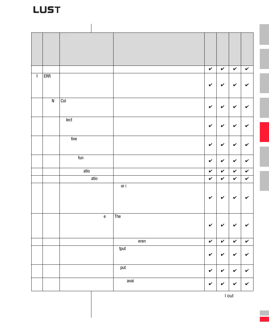
Settings for 240-FOS00, ... 246-FOE03
BUS KP/ DM Function Effect
F
O
S
0
0
F
O
S
0
1
F
O
S
0
2
F
O
E
0
x
0 OFF No function Output off
1 ERR Collective error message Device in error state. The error must be eliminated
and acknowledged before operation can be
restarted.
(Section 5.3.10 “_51ER-Error messages”)
2 WARN Collective warning message Parameterizable warning limit exceeded, device still
ready.
(Section 5.3.9 “_50 WA-Warning messages”)
3 /ERR Collective error message
negated
Device in error state. The error must be eliminated
and acknowledged for operation to be restarted.
(Section 5.3.10 “_51ER-Error messages”)
4 /WARN Collective warning message
negated
Parameterizable warning limit exceeded, device still
ready. Wire-break-proof output.
(Section 5.3.9 “_50 WA-Warning messages”)
5 ACTIV Control in function Power stage active and closed-loop/open-loop con-
trol control in function
6 ROT_ R Clockwise rotation Motor running clockwise
7 ROT_L Anti-clockwise rotation Motor running anti-clockwise
8 ROT_0 Motor at standstill Motor in standstill window (f=0 Hz).
Control mode FOR: Safe standstill message.
Control mode SFC: Dependent on estimated speed
Open-loop control mode VFC: Dependent on refer-
ence value.
9 LIMIT Reference limitation active The internally processed reference value exceeds
the reference limit and is restricted to the limit
value.
(Section 5.3.1 “_30 OL-Frequency limitation”)
10 REF Reference reached The preset reference has been reached.
11 SIO Access by control word of
LustBus
Output can be set via the serial interface by the
L
USTBUS CONTROL WORD.
(Section 5.4.1 “_55 LB-L
USTBUS”)
12 OPTN1 Reserved for option module,
slot 1
Output available to option module at slot 1. Usable
only in conjunction with communication modules.
13 OPTN2 Reserved for option module,
slot 2
Output available to option module at slot 1. Usable
only in conjunction with communication modules.
Table 5.21 Settings for function selector FOxxx of the digital outputs
 Loading...


