Application Manual CDA3000
4-23
4 Application data sets
1
2
3
4
5
6
A
DE
EN
FR
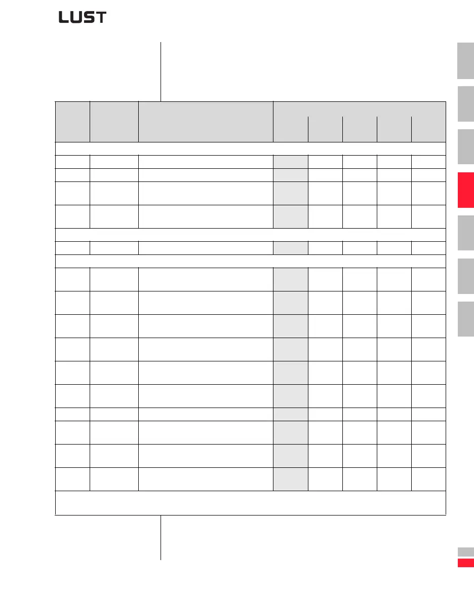
4.3.6 Comparison of
parameters,
traction and
lifting drive
Comparison of application data sets for traction and lifting drives with
the factory setting (152-ASTER = DRV_1):
I/O Parameter Function
152-ASTER =
DRV_1
(FS)
DRV_2 DRV_3 DRV_4 DRV_5
Initial commissioning
151-ASTPR Original device preset DRV_1 DRV_2 DRV_3 DRV_4 DRV_5
152-ASTER Preset within the active application data set DRV_1 DRV_2 DRV_3 DRV_4 DRV_5
166-UDSSL
Control location for switchover of the active
user data set
PARAM 1) 1) 1) 1)
300-CFCON
Current open-loop/closed-loop control
mode of the device
VFC FOR FOR
Driving profile generator
597-RF0 Response at reference value 0 Hz OFF 0 Hz 0 Hz
CDA3000 inverter module inputs and outputs
ISA00 180-FISA0
Function selector analog standard input
ISA00
OFF UM0 UM0 UM0
ISA01 181-FISA1
Function selector analog standard input
ISA01
OFF UM1 SADD1 UM1
ISD00 210-FIS00
Function selector digital standard input
ISD00
STR
ISD01 211-FIS01
Function selector digital standard input
ISD01
STL
ISD02 212-FIS02
Function selector digital standard input
ISD02
SADD1 /LCW ENC ENC
ISD03 213-FIS03
Function selector digital standard input
ISD03
OFF CUSEL /LCCW ENC ENC
OSA00 200-FOSA0 Function selector for analog output OSA00 AACTF
OSD00 240-FOS00
Function selector digital standard output
OSD00
BRK_1
OSD01 241-FOS01
Function selector digital standard output
OSD01
REF
OSD02 242-FOS02
Function selector digital standard output
OSD02
S_RDY
1) After setting the parameters of the user data sets, change parameter value 166-UDSSL from PARAM (KEYPAD KP200,
D
RIVEMANAGER) to TERM (terminal operation).
Table 4.12 Automatic changes by means of the assistance parameter