Application Manual CDA3000
3-9
3 User interface and data structure
1
2
3
4
5
6
A
DE
EN
FR
3.3 Operation with
K
EYPAD KP200
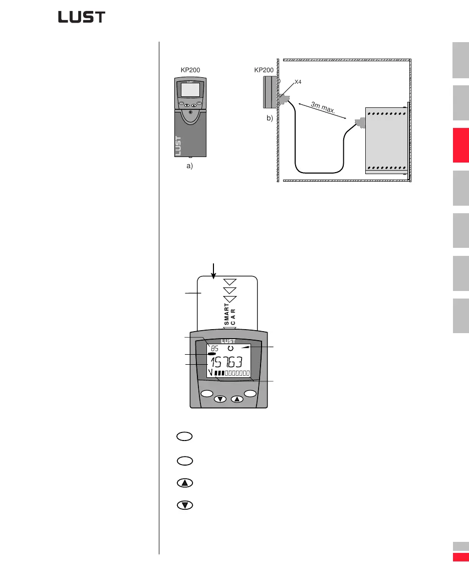
Mounting and connection of the KEYPAD
Figure 3.3 Mounting the KEYPAD: a) on the CDA3000 inverter module (con-
nector X4) or b) on the switch cabinet door
Controls and displays
(1)
Chipcard (S
MARTCARD) to back-up and
transfer settings
(2)
3-digit display, e.g. for parameter
number
(3) Current menu
(4)
5-digit display for parameter name and
value
(5) Acceleration or braking ramp active
(6) Bar graph display, 10-digit
Call up menu branches or parameters; save changes;
Start in “Control drive” mode
Quit menu branches; cancel changes; stop in “Control drive” mode
Select menu, subject area or parameter; increase setting
Select menu, subject area or parameter; reduce setting
Figure 3.4 Controls and displays on the K
EYPAD KP200
3m max.
KP200
KP200
a)
b)
start
enter
stop
return
X4
SMART
CARD
start
enter
stop
return
VAL
Hz
(2)
(1)
(6)
(4)
(3)
(5)
start
enter
stop
return