4-22
Application Manual CDA3000
4 Application data sets
The parameter presets for application data sets DRV_x are located as
parameter comparison references in section 4.3.6 “Comparison of para-
meters, traction and lifting drive”.
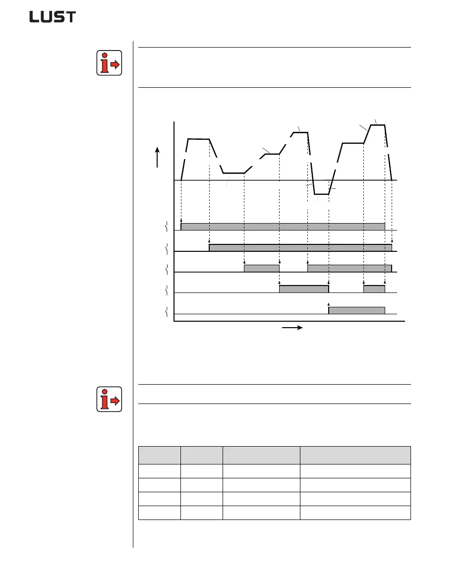
Input signals
v/t diagram
Figure 4.16 Example of use of table sets with fixed frequencies and ramps
(ASTER=DRV_5)
The output signals are presented in section 4.3.1 “DRV_1” in Figure 4.4.
User data set switchover (switchable offline)
S7 S8 Active UDS Example
0 0 UDS 1 for application 1 x-axis, traction drive
1 0 UDS 2 for application 2 y-axis, traction drive
0 1 UDS 3 for application 3 z-axis, lifting drive
1 1 UDS 4 for application 4 Sorting belt
Table 4.11 User data set switchover
t [ms]
0
f [Hz]
v [m/s]
0
1
0
1
0
1
S3
S2
S1
0
1
STR
0
1
S4
303-FMAX1
600-FFTB0
601-FFTB1
602-FFTB2
604-FFTB4
TDCR4
615-TACR7
602-FFTB7
590-ACCR1
608-TACR0
609-TACR1
610-TACR2
619-TDCR3
611-TACR3
603-FFTB3
612-TACR4
594-STPR1