Application Manual CDA3000
5-133
5 Software functions
1
2
3
4
5
6
A
DE
EN
FR
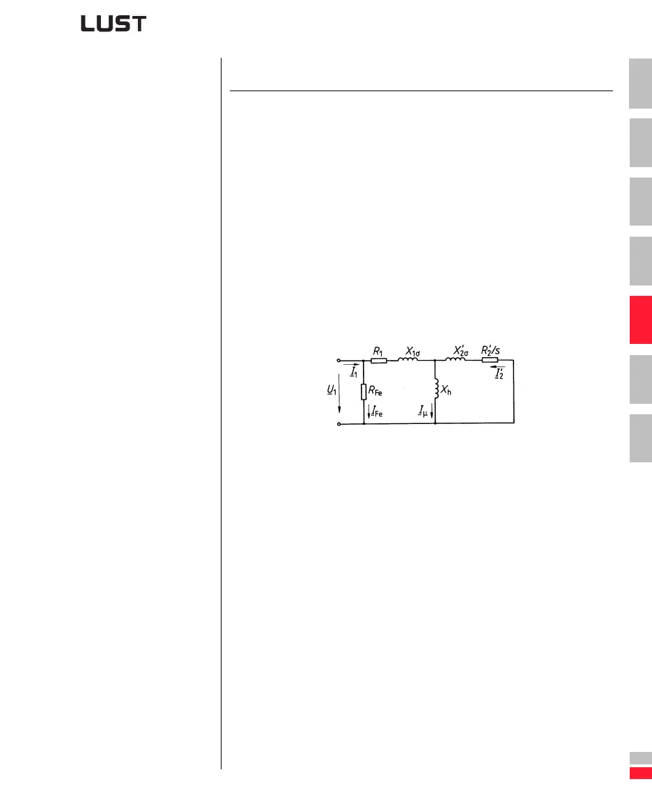
Simplified equivalent circuit diagram of the asynchronous
machine
s Slip
X
h
Magnetizing inductance
R
1
Stator phase resistance
R
2
Rotor resistance
X
1σ
Stator leakage inductance
X
2σ
Rotor leakage inductance
R
FE
Core loss resistance
I
M
Magnetizing current
Explanatory notes
• The fields marked with an asterisk (*) are dependent on the rated
power of the inverter module.
• In the factory setting the typical data of an IEC asynchronous stand-
ard motor of the device rated power are entered in the parameters.
• During auto-tuning of the inverter module (163 -ENSC=START) the
motor data are acquired in the course of initial commissioning. The
precondition for this is correct input of the motor rating plate data.
• All motor data can be transferred by way of the S
MARTCARD or the
D
RIVEMANAGER. The parameters of the current and speed control
loops should additionally be transferred so that the motor can be run
correctly on the inverter module.
 Loading...


