262335 14 Revision A
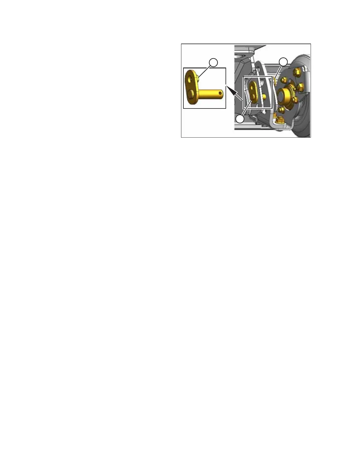
Figure 3.8: Gauge Roller and Locking Pin
8. Remove locking pin (A) and adjust rollers to desired height.
Reinstall both locking pins (A).
9. Ensure that nut (B) on each pin registers in adjacent hole in
support bracket.
10. Secure pins with hairpins (C).
11. Repeat previous steps for opposite side. Set both gauge
rollers to the same position.
ASSEMBLING THE MACHINE