214325 63 Revision A
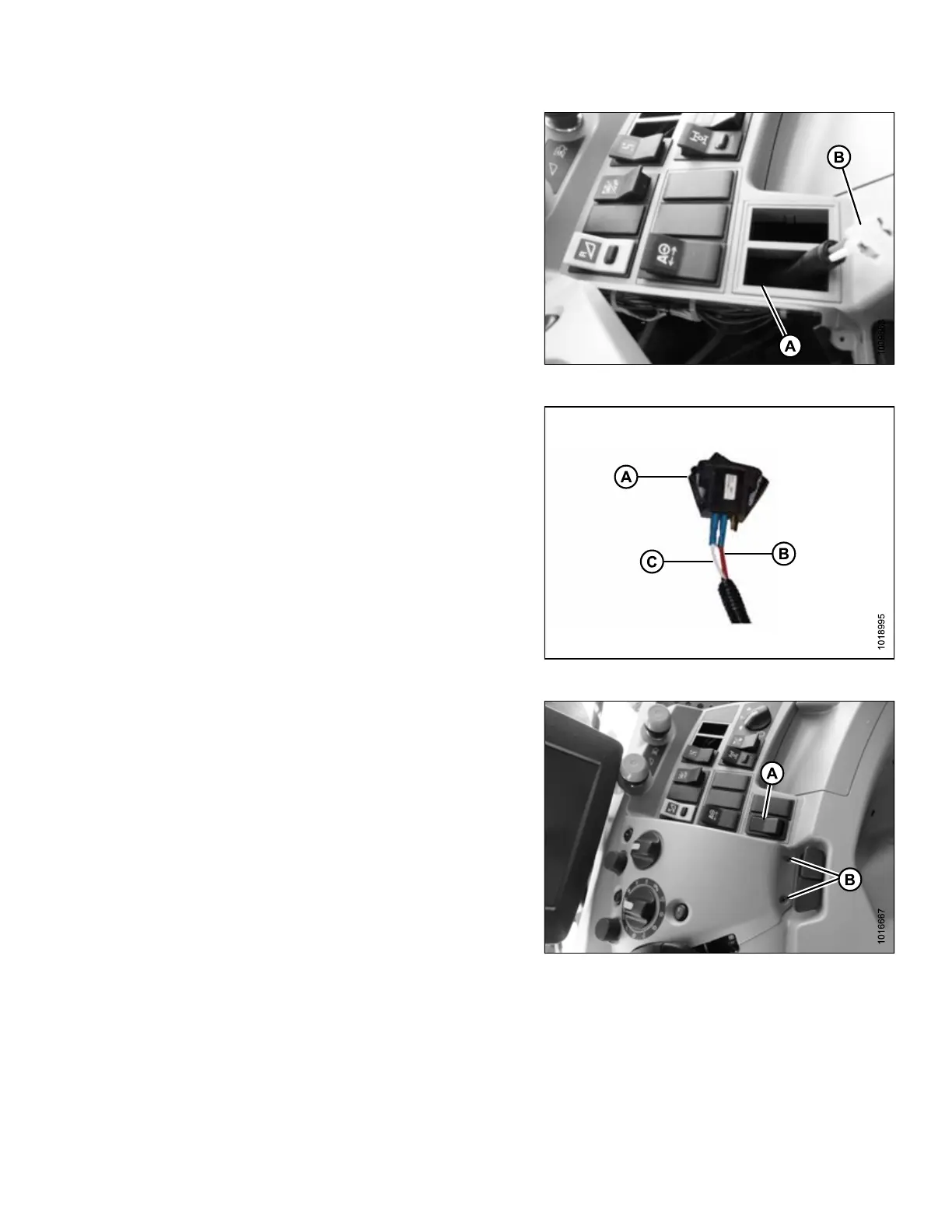
Figure 3.108: Switch and Console
4. Remove a blank cap from operator’s panel at
location (A). If LASER PILOT autosteer switch is
installed, select the blank plug next to it for location of
rocker switch.
5. Route switch end (B) of MacDon harness through
opening (A).
Figure 3.109: Switch Connection
6. Retrieve rocker switch (A) from shipping package.
7. Connect red wire (B) at switch end of harness to center
terminal of rocker switch (A).
8. Connect white wire (C) at switch end of harness to
either outer terminal of rocker switch (A). It does not
matter which outer terminal is used.
NOTE:
Some MacDon wiring harnesses have two red wires
instead of one white and one red. In that case, connect
one red wire to the center terminal and the second red
wire to either outer terminal. It does not matter which
outer terminal is used.
Figure 3.110: Console
9. Snap rocker switch (A) into the panel from the top.
10. Replace cover onto console and secure with the two
previously removed screws (B).
11. Locate power source for the switch. Refer to the
following procedures as necessary:
IMPORTANT:
Location depends on combine model. A switched power
source is either inside the terminal compartment on the
cab floor, or behind a removable panel beside the
ignition switch. If there is no switched power available,
unswitched power or a cigarette lighter adapter may
be used.
If on-floor power source:
ASSEMBLING HEADER AND ADAPTER