Section 5 – INSPECTION
Mini-Crawler Crane M A E D A
5-16 9/2020 MC285CB-3
Check Fuses
NOTICE: If fuses blow frequently, inspect and
repair the cause of failure immediately before
continuing operation.
See “FUSES” on page 5-12 for more information
on fuse locations.
If a fuse has blown or an open/short circuit is
found in the electrical wiring, contact us or our
sales service agency to request inspection and
repair service.
Check Cracks, Deformation or Damage
of Boom and Frame
Check the boom and frame for cracks,
deformation or any other damage, and correct
them if anything abnormal is found.
Check Deformation, Damage or Wear of
Wire Rope
Check the rope end fixing, rope take up condition
and contact between the ropes. For the check and
inspection of wire rope while winch and boom
telescoping, see “Wire Rope” on page 5-41.
Check Electric Wiring
Check the electric wiring and inspect to ensure
that wiring has not been disconnected, damaged,
or burnt out, and that connectors are not
disconnected.
Pre-Start Inspection
Check / Add Hydraulic Oil
Before checking or adding hydraulic oil, read the
maintenance precautions in “Handling and
Service of Hydraulic Oil and Filters” on page 5-4.
WARNING! The following safety messages
address a potential Burn Hazard:
• Parts will still be hot immediately after
stopping machine operation. Do not carry
out work immediately. Wait until the oil has
cooled. (45°C or less)
• Relieve internal pressure by slowly rotating
the hydraulic tank air breather cap during
removal.
• Make sure the hydraulic tank air breather
cap is closed properly after adding oil.
• When filling the hydraulic oil tank, do not fill
above the upper limit on the level gauge.
Overfilling may cause oil to gush from the
tank during machine operation.
If the tank interior is still pressurized when the air
breather cap is removed, the element may be
clogged. Inspect the air breather.
For information on the air breather inspection, see
“Air Breather Inspection” on page 5-49.
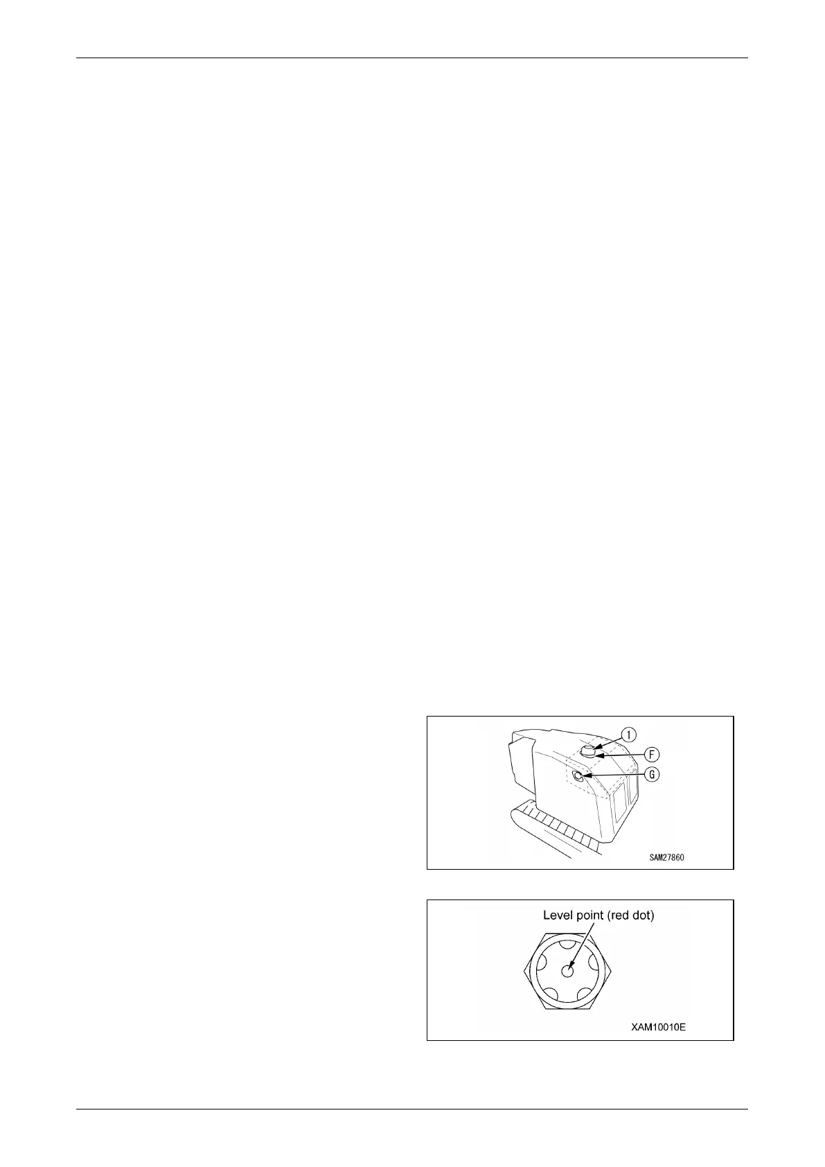
1. Stop the machine on a level surface in the
travelling posture.
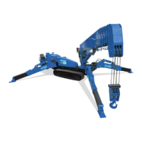
2. Check the oil level gauge (G) in the left side of
the machinery cover and ensure that oil is
sufficient to reach the level point (red point).
Fig. 5-9
Fig. 5-10