Section 4 – OUTRIGGER SETTING MODES Mini-Crawler Crane M A E D A
4-48 9/2020 MC285CB-3
OUTRIGGER SETTING
MODES
Make sure all outriggers are placed properly
before performing crane operation. This
machine features a safety-interlock system that
prevents crane operation unless all lights, other
than the Boom Stowing Light on the outrigger
monitor, are on.
Always place the machine in a horizontal
position using the level when extending the
outriggers. An inclination alarm sounds when the
machine is tilted 3 degrees or more and stops
when the machine is placed in a horizontal
position.
WARNING! Tip Hazard. Do not operate the
machine if the inclination alarm sounds and
the machine is tilted greater than 3 degrees.
The tilt of the machine must be less than 3
degrees for proper operation.
Before using the crane with the outriggers not
fully extended, know the limitation of the
machine. Determine safe operation by referring
to the rated total load for the "Other than MAX"
outrigger position in “RATED TOTAL LOAD
CHARTS” on page 3-13.
WARNING! Tip Hazard. Only operate the
crane within the guidelines indicated for the
"Other than MAX" outrigger position in
“RATED TOTAL LOAD CHARTS” on page
3-14 when the outriggers are not fully
extended. For proper operation of the
machine, do not exceed these guidelines.
WARNING! Tip Hazard. Always rotate a
hoisted load slowly, in the 360-degree
slewing position, using a short working
radius and with the motor at low speed,
regardless of the load size. The machine
could become unsteady if a short working
radius is not used and the motor is operating
at a high speed.
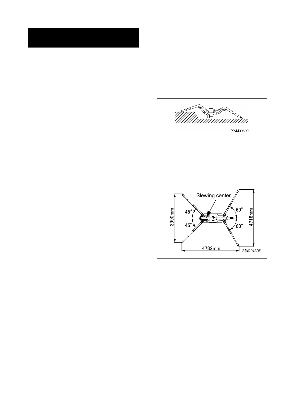
"MAX" Outrigger Position
When the outriggers are set at the fully extended
position on uneven ground, the width of the
extended outriggers deceases, even when there
is 80 mm of clearance between the bottom of the
rubber tracks and the ground. See “RATED
TOTAL LOAD CHARTS” on page 3-10 and
“"Other than MAX" Outrigger Position” on page
4-49.
Fig. 4-121
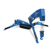
The "MAX" outrigger position is shown in the
figure below. See “RATED TOTAL LOAD
CHARTS” on page 3-10 and the rated total load
indicated for outriggers extended to maximum
for additional information.
Fig. 4-122
If the inner box is retracted even slightly, crane
operation should proceed referring to the rated
total load for the "Other than MAX" outrigger
position in “RATED TOTAL LOAD CHARTS” on
page 3-10.
See “OUTRIGGER SETTING” on page 4-43 for
proper setting of the outriggers.