Section 4 – RADIO REMOTE CONTROL SYSTEM OPERATION Mini-Crawler Crane M A E D A
4-110 9/2020 MC285CB-3
Outrigger Setting
WARNING! Before setting outriggers, read
“OUTRIGGER SETTING” on page 4-43 and
also the precautions described there.
Operations performed with machine shut
down
1. Set the outriggers as described in
“Procedures When Stopping the Machine” on
page 4-44.
Fig. 4-269
Operations after Starting Machine
WARNING! If the machine tilts at an angle of
“3 degrees” or more while the outriggers are
set, the overturn warning buzzer sounds. Use
the levers to adjust the level of the machine so
that the warning buzzer does not sound.
1. Push in the travel lever on the machine main
unit while unlocking the lever to enable
operation of outriggers.
Fig. 4-270
NOTICE: If the travel lever is not pushed in, the
interlock will engage and prevent outrigger
operations.
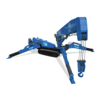
2. Switch the operation mode selector switch to
“Outrigger.”
Fig. 4-271
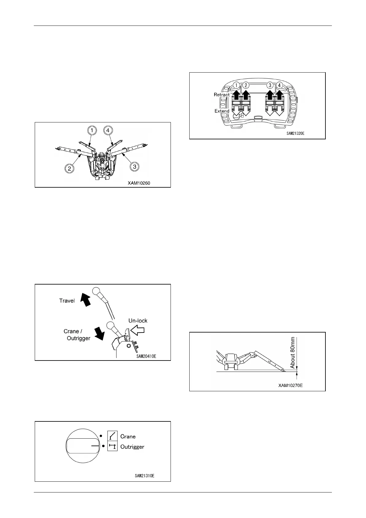
3. Use the levers to extend all four outriggers
until they are in contact with the ground. Stop
operating each outrigger once it makes
contact with the ground.
Fig. 4-272
• Ground Set-Up: The outriggers are lowered
to the ground.
• Stowage: The outriggers are lifted from the
ground.
NOTICE: When using the radio remote control
system, there are no levers to operate all four
outriggers simultaneously or to operate the front
or rear outriggers simultaneously. To operate
multiple outriggers, operate the corresponding
operation levers simultaneously.
4. Once all outriggers are in contact with the
ground, operate the levers once again in the
ground contact direction.
Operating the both front or rear operation
levers at a time or operating all four levers
together will make it easier to adjust the
height. Repeat this ground contact procedure
to gradually lift the machine off the ground
until the rubber tracks are approximately 80
mm above the ground.
Fig. 4-273
5. Once the machine has been lifted
approximately 80 mm above the ground,
check the position of the bubble in the
monitor level gauge to level the machine
body.