Section 3 – RATED TOTAL LOAD CHARTS Mini-Crawler Crane M A E D A
3-10 9/2020 MC285CB-3
RATED TOTAL LOAD
CHARTS
WARNING! Tip Hazard. Never exceed the
maximum load limit per working radius stated
in the Rated Total Load Charts. Always
operate the crane and boom within these
limits.
The Rated Total Load Charts indicate the
maximum loads the crane is capable of hoisting in
parallel with the length of the boom. The loads are
specified by working radius.
All the values provided in the Rated Total Load
Charts are based on the assumption that the
machine is placed on a level, solid surface.
The values in the Rated Total Load Charts are
determined based on the working radius, allowing
for deflection that is developed when load is
applied to the boom.
The Rated Total Load Charts are the same in all
directions regardless of the slewing stop position.
When extending boom no. 3 even slightly, crane
operation should proceed to the extent of
performance of boom configuration range
4.080-5.575 m.
When half of the first “ mark” passes boom no. 3,
crane operation should proceed to the extent of
performance of boom configuration range
5.580-7.075 m.
When half of the second “ mark” passes boom
no. 3, crane operation should proceed to the
extent of performance of boom configuration
range 7.080-8.575 m.
If the working radius exceeds that stated in the
table even slightly, crane operation should
proceed with respect to the rated total load
corresponding to the working radius.
The rated total load includes the mass of the
hoisting accessory (rigging and hook block).
When the crane is used with the outriggers
extended other than at maximum extension, crane
operation should proceed with respect to the
values specified in the Rated Total Load Chart
corresponding to “When the crane is used with the
outriggers extended at the other than maximum.”
Programmable Moment Limiter
WARNING! Tip Hazard. The following
precautions should always be observed when
reading the “rated total load” provided by the
programmable moment limiter.
• The outriggers should be placed on a level
and firm surface.
• The outriggers should be at maximum
extension as much as possible.
• The weight of an object, including that of a
hoisting accessory and slinging rope, must
remain below the rated total load for hoisting
objects. With the boom length (number of
stages) and angle specified, make a
comparison between the rated total load
provided by the programmable moment
limiter and the weight of the object.
The programmable moment limiter provides
readouts on the rated total load under the
following conditions:
• The outriggers are placed on a level and firm
surface.
• No deflection is developed in the boom.
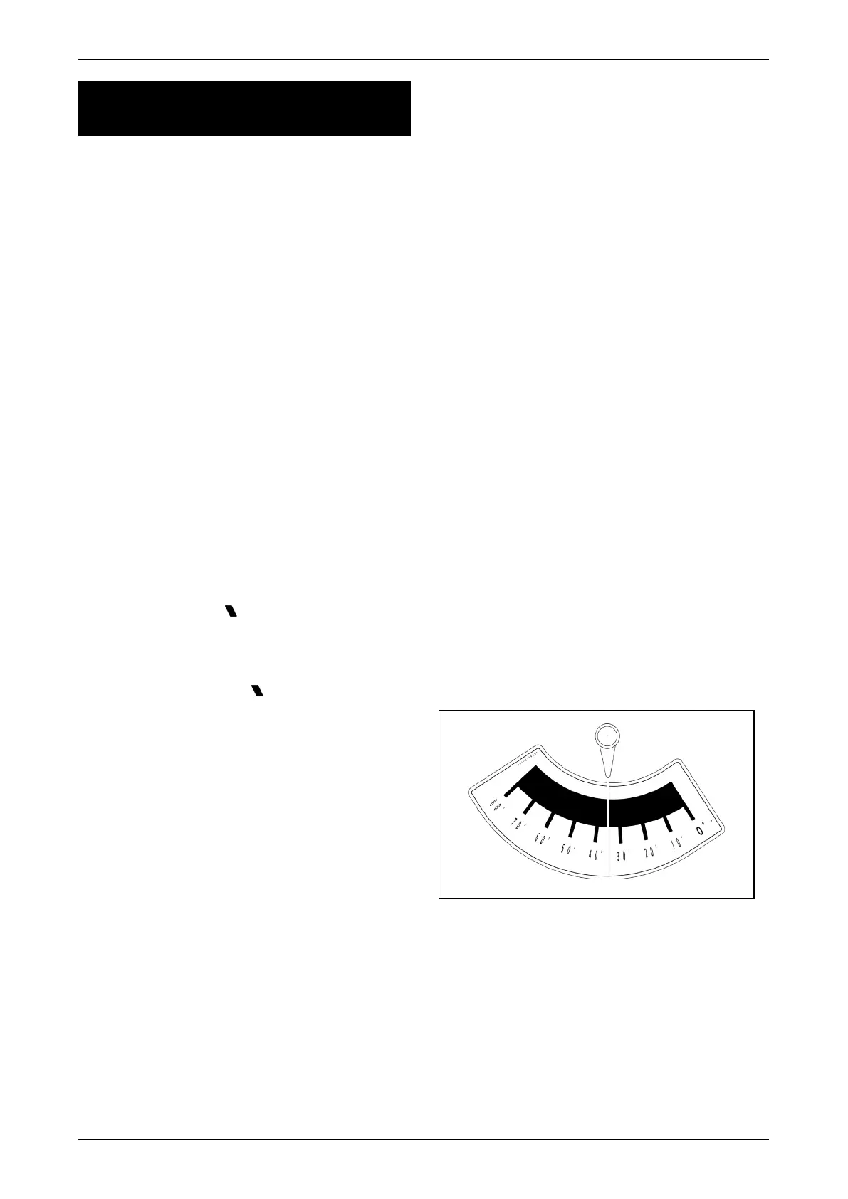
Reading the Angle Indicator
The intersection point of the pointer that is
attached to the, and the label on the boom, is the
current boom angle. The boom angle shown in the
figure below is 35°.
Fig. 3-9