Section 5 – GENERAL MACHINE MAINTENANCE
Mini-Crawler Crane M A E D A
5-38 9/2020 MC285CB-3
A steel pipe is required for the following
procedure.
1. Set the outriggers and raise the tracks
approximately 50 mm from the ground. See
“OUTRIGGER SETTING” on page 4-43.
2. Remove the two screws (2) and cover plate
(1).
Fig. 5-70
3. Loosen the grease valve (3) slowly and
remove grease. Do not turn the grease valve
more than one full turn out.
Fig. 5-71
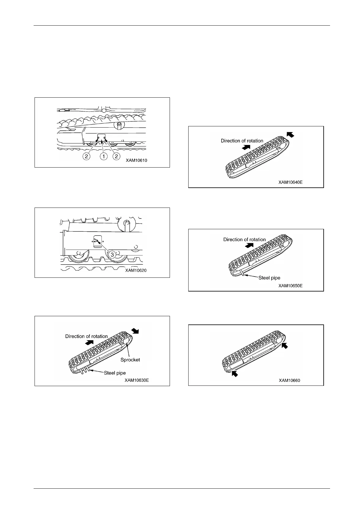
4. Insert the steel pipe between the idler and
rubber track, as shown below, and rotate the
sprocket backward.
Fig. 5-72
5. After the rubber track is free from the idler,
slide the crawler in a lateral direction to
remove it.
Installation of Rubber Tracks
A grease gun and steel pipe are required for the
following procedure.
1. Set the outriggers and raise the tracks
approximately 50 mm from the ground. See
“OUTRIGGER SETTING” on page 4-43.
2. With the rubber track engaged with the
sprocket, install the crawler on the idler.
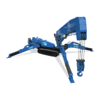
3. With the sprocket rotating backward, push
the rubber track in to stop rotation.
Fig. 5-73
4. Insert the steel pipe between the idler and
rubber track again, and rotate the sprocket to
install the crawler on the idler.
Fig. 5-74
5. Stop rotation and ensure that the rubber track
is on the sprocket and idler properly.
Fig. 5-75
6. Adjust the rubber track tension.
See “Checking Rubber Track Tension” on
page 5-39 and “Adjusting Rubber Track
Tension” on page 5-39.
7. Stow the outriggers and lower the machine to
the ground. See "OUTRIGGER STOWING"
on page 4-53.