Installation and User Manual
23
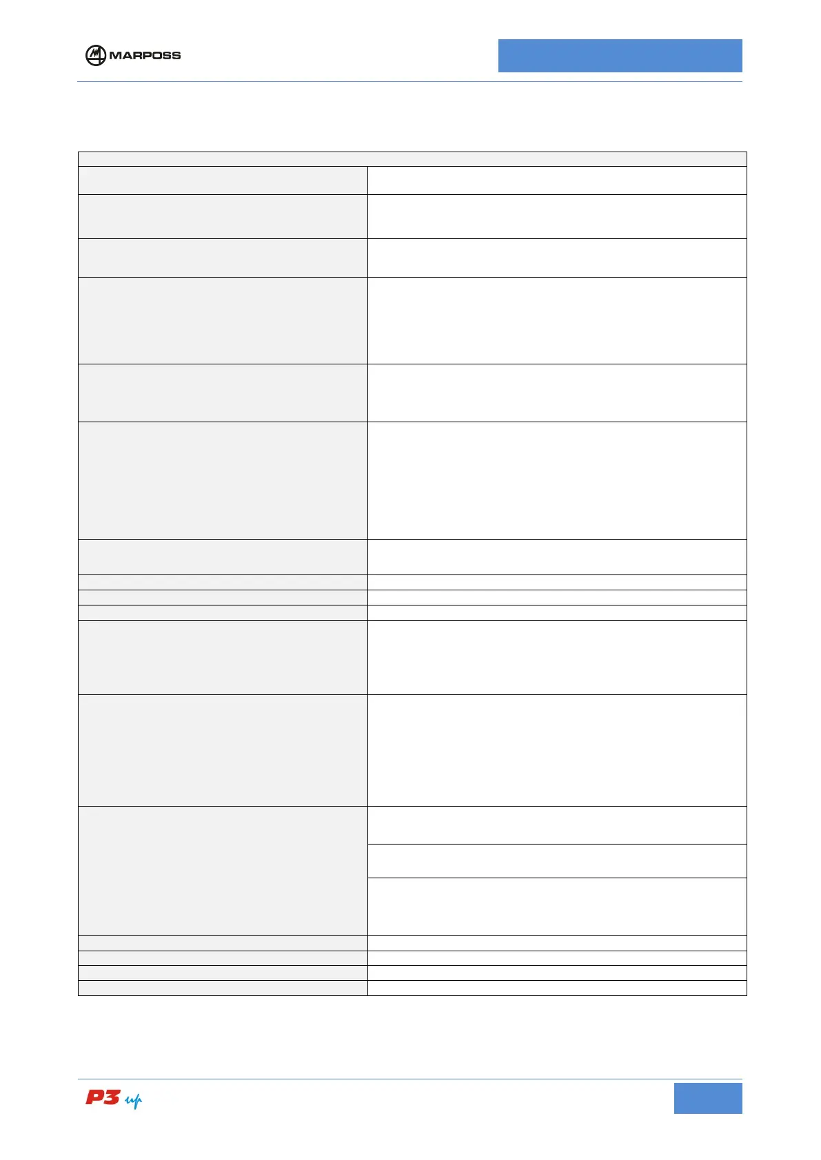
5.3
General technical specifications
Table 5-1 P3UP technical specifications
STRUCTURE
Case or panel mounted
CHANNELS
For connection to Marposs LVDT or Air-
Gap type measurement
heads with or without retraction
MEASURING CYCLES
In-process grinding checks
MEASUREMENT RANGE
(In-process cycle)
According to dial indicator scale:
100-0-20 (+1000 to -200 μm)
50-0-10 (+500 to -100 μm)*
10-0-2 (+100 to -20 μm)
*N.B. also available in inches
POWER SUPPLY
“100-230 V a.c., r.m.s (-15% / +10%), 50-60Hz (-6% - +5%)
It complies with the electrical safety standard for the power supply
voltage interval indicated,
however the gauge has been designed
to work also with input voltage up to 85 V a.c.
POWER CONSUMPTION
• 15 W without retraction option and no I/O or Type B I/O
• 20 W without retraction option and Type A or Type C I/O
• 40 W with series retraction and all I/O types
•
30 W with parallel retraction and all I/O types (55 W max peak
value when retraction is activated)
Current consumption: 0.7 A a.c. r.m.s.
Inrush current: 60 A r.m.s.
POWER On/Off LED
On front panel
5° to 40° C / 41°F to 104°F
-20° to 60° C / -4°F to 140°F
PROTECTION DEGREE
(Standard IEC 60529)
• Panel version mounted so as to guarantee the seal at the
point contact between
the frame and the panel (using a gasket
or similar system): IP54 on front panel
• Cabinet version: IP30
• Panel mounted version IP20
MACHINE LOGIC INTERFACE (I/O)
Opto-isolators or relays:
I/O TYPE A (Outputs with N.O. contacts relays)
I/O TYPE B (Opto-isolators output)
I/O TYPE C (Outputs with exchange relays)
See para. 6.3
ANALOGUE OUTPUT
T1 10mV/µm
T2 10mV/µm
In-process measurement (according to dial indicator)
10 mV/μm (scale 100-0-20)
20 mV/μm (scale 50-0-10)
100 mV/μm (scale 10-0-2)
ELECTRICAL SAFETY STANDARD
ELECTRO-MAGNETIC COMPATIBILITY