Installation and User Manual
62
7.1
Mechanical zero-setting the instrument
If the instrument index is not perfectly positioned on the zero when the unit is switched off, adjust the screw
located underneath the protective cap. This operation must always be carried out when the unit is switched
off, observing the various precautions regarding electro-static discharges in the note on page 60. Once the
adjustment has been completed, replace the protective cap.
7.2
P3UP in measurement
When it is switched on the P3UP enters measurement mode. The In-Process head measurement is
performed when channel ∑ is selected (channels T1 and T2 are only used to display the individual In-
Process head transducers).
The gaP3UP features two operating modes:
• MANUAL MODE : in this mode, only the START CYCLE, MEMORY CONTROL, HEAD
RETRACTION and PULSE FEEDBACK machine logic inputs are active, whereas the outputs to the
machine logic are not active (the only two outputs that are updated are ALARM and OVR FEEDBACK, if
present). In manual mode, the state of the controls during the measurement cycle is indicated by the
LEDs on the panel.
•
AUTOMATIC MODE : all the inputs and the outputs to the machine logic are active.
In both operating modes it is possible to:
• Set-up the grinder advance commands trigger thresholds
• Select the channels to be used
• Correct the measurement value using Zero Adjust
• Correct the measurement value using Pulse Feedback
[
When in measurement mode, wait for three seconds after applying the last modification to one
of the data listed above before switching the unit off. The P3UP memorises the state of the
panel three seconds after the last time it is used.
[
If the SUM SAFE safety function
is active it is possible to enter automatic mode only if the
machine is in ∑. This function is a factory pre-set and may be deactivated if requested by the
7.2.1
Setting up the control points
To set-up the control points, proceed as follows:
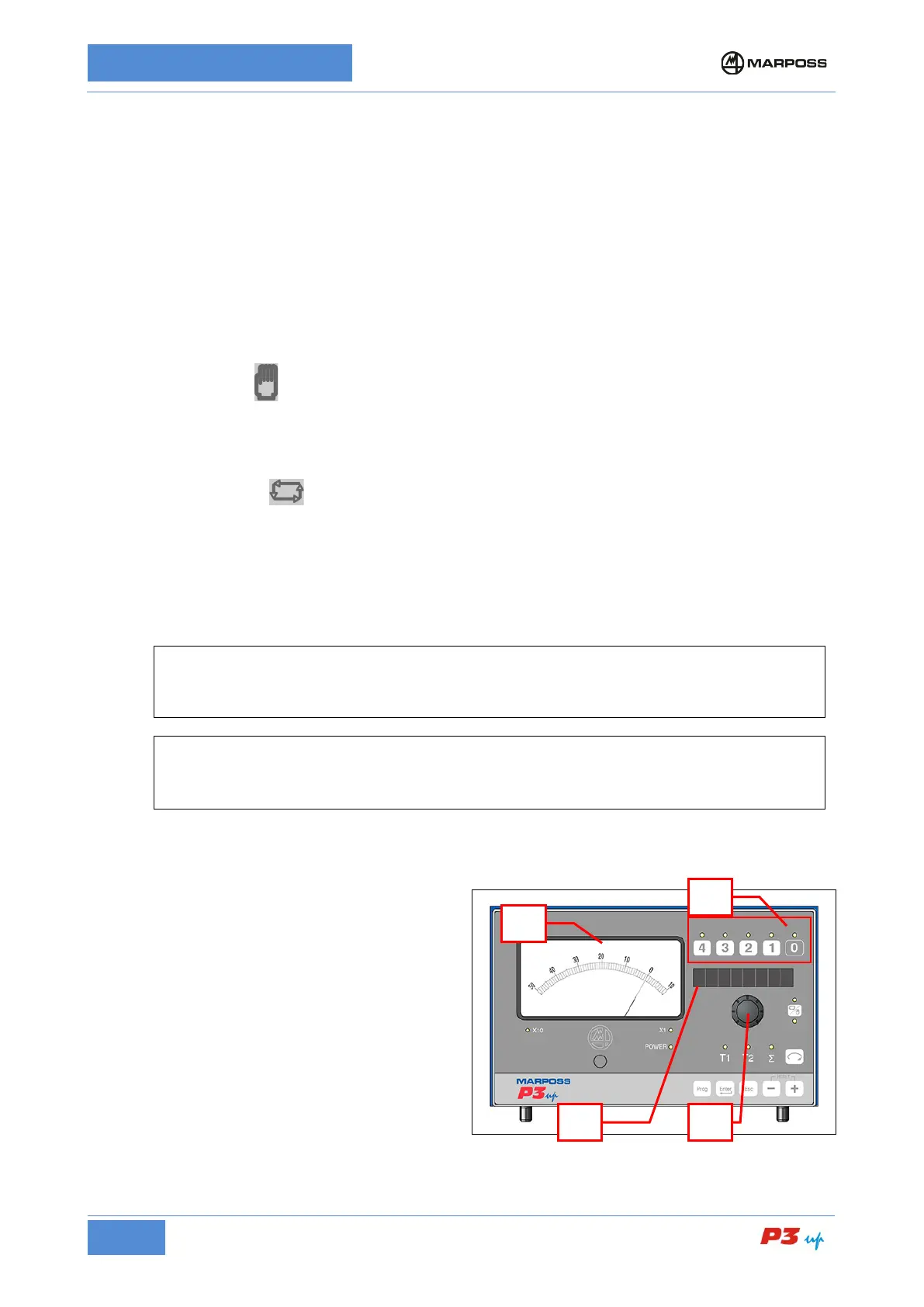
1.
Press (and hold) the button corresponding to
the control (D).
2.
The name of the control appears on the
alphanumerical display (A) (or the abbreviation
N.A. if the control is not active).
3. Rotate the knob (B)
until the desired control
point value is displayed on the instrument (C).
The number of active controls is defined during
the programming phase (see para.
0).