Installation and User Manual
36
6.3.2
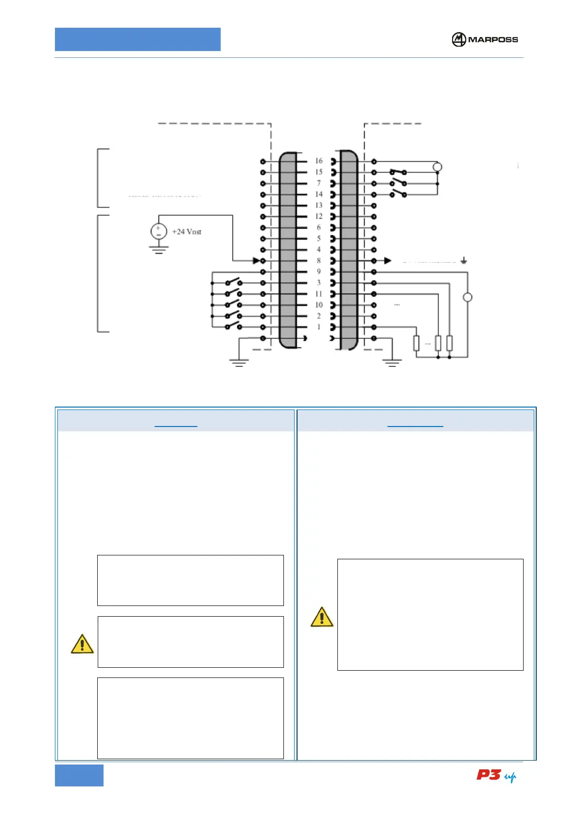
I/O TYPE AA – Outputs with N.O. contacts relays
H1 connector wiring diagram for I/O TYPE AA
N.B.:
** = based on the configuration.
INPUTS OUTPUTS
1. SINK/SOURCE current, 24 V d.c. drive. The
SINK/SOURCE current connection for the inputs can
be selected by connecting the in
terminal.
Electrical specifications:
• input active
V
I
(ON) = 15 to 30 V d.c
I
I
(ON) = 10 mA (V
I
= 24 V d.c), 6 to 12 mA (V
I
=
15 to 30 V d.c.)
• Input deactivated
V
I
(OFF) = (−3 to 5) V d.c.,
N.B.
the SINK current type inputs connection
feat
ures specifications that are compatible
with the "TYPE 1" digital inputs as defined in
the Standard EN61131-2.
WARNING
The machine inputs must be supplied by a
SELV (Safety Extra Low Voltage) power
source, as defined in the Standard EN60950-
N.B.
The “SINK current” input is driven by a switch
or limit switch connected between the input
itself and the positive pole of the machine I/O
power supply. The SOURCE current input is
driven by a switch or limit switch connected
between the input itself and
the negative pole
of the machine I/O power supply.
Relay with N.O. contact (Normally Open = closed
when active)
• Maximum current per contact: 3 A, with
restive load
• Maximum relay common contact current:
3.5 A
• Maximum voltage: 250 V a.c. r.m.s., 50-60
Hz (-6% / +5%) or 30 V d.c.
• Parasitic current for each open contact: 2
mA max (250 V a.c.)
ATTENTION
The outputs are not protected: install on the
shared outputs a magnetothermic protection
device with nominal current not greater than
In= 4A, characteristic “B” in compliance with
EN60947 and magnetic trigger current not
greater than 4 In= 16A or an equivalent fuse.
It is left to the user's discretion whether to
protect the individual outputs with a suitable
device. The power supply should also be
fitted with a differential circuit breaker
INPUTS COMMON
START CYCLE
OUTPUTS COMMON
AUTO
power
supply
User’s logic (ex.CNC,PLC,etc.)