Installation and User Manual
22
5.2
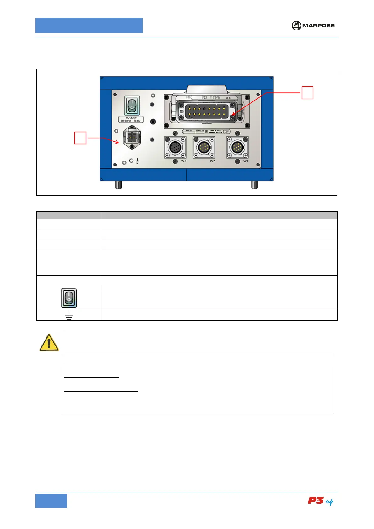
Description of connectors
Male 10-pin connector for measurement head 1.
Male 10-pin connector for measurement head 2.
Female 10 pin connector for the analogue output connection.
H1
Heavy Duty 16 pin connector for the I/O interface signals with the machine logic
See para. 6.3.
N.B. Some pins may not be present, depending on the specific model.
Electrical power supply connector. See para. 6.5
P3UP ON/OFF switch
Earth stud (M5).
WARNING
* Use Marposs measurement head switch connectors W1 and W2.
[
P3UP WITH CASE: Position the unit so that it is not difficult to remove the due power supply
connectors (A and H1 in Figure 5: P3UP rear view)
PANEL MOUNTED P3UP
: Must be fitted with a switching device that can be used to isolate the
unit from its two power supplies A and H1 in fig Figure 5: P3UP rear view).
The switching device must isolate all the power supply conductors and be easy to access and
operate. It must not be necessary to use any kind of tool to operate it.