Installation and User Manual
42
6.3.4
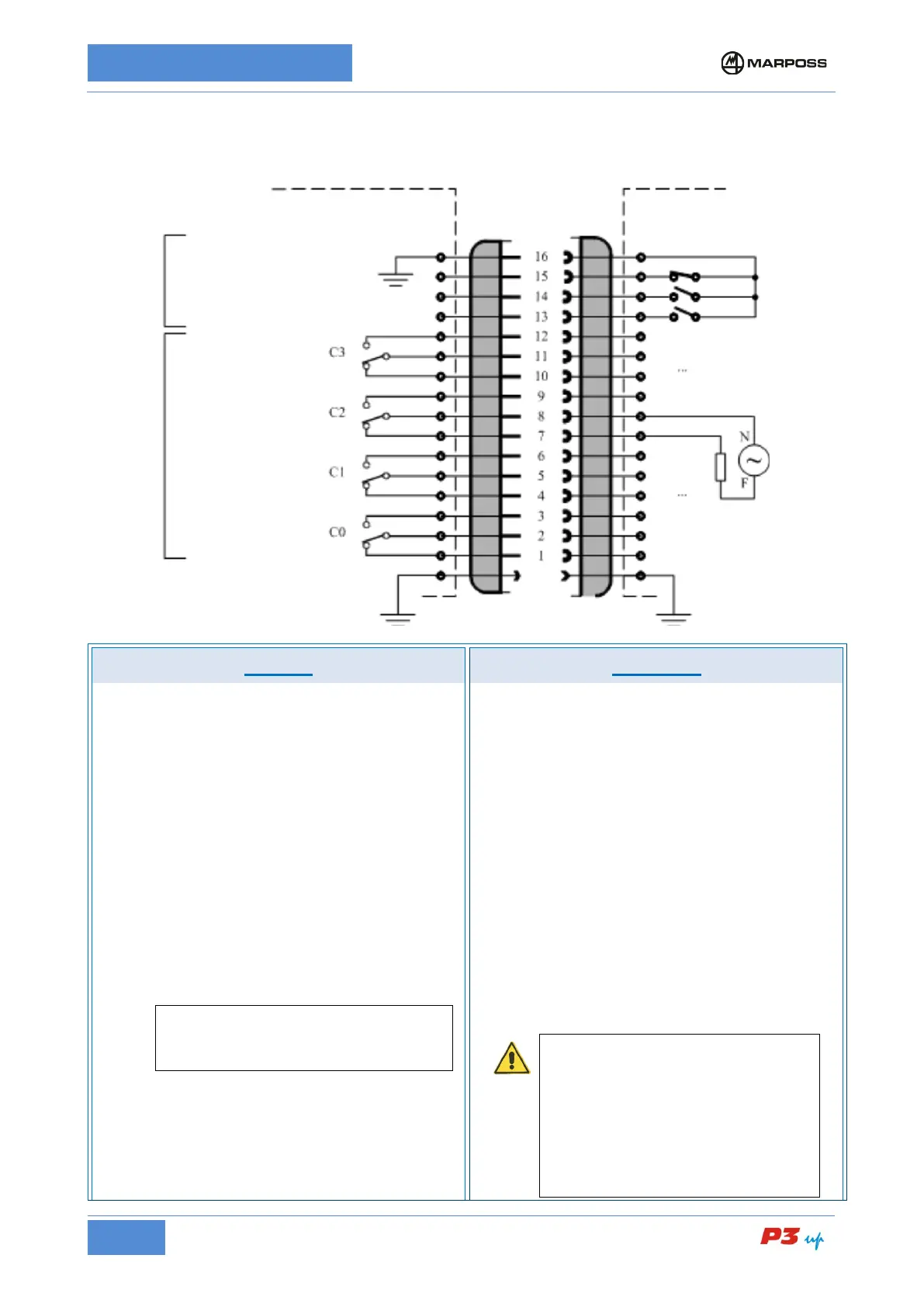
I/O TYPE C – Outputs with exchanged relays
H1 connector wiring diagram for I/O TYPE C1
INPUTS OUTPUTS
The inputs are “current SOURCE” type and supplied
by the internal power source.
Electrical specifications:
input active
• The inputs are activated by being connected to
the inputs common (terminal 16),
• Maximum contact resistance: 100 Ohm
• Maximum voltage drop on contact: 1.1V
• current output I
I
(ON) <= 10 m A d.c.
Input deactivated
• The inputs are deactivated by disconnecting
them from the inputs common (terminal 16),
• Maximum contact resistance: 100kOhm (or loss
current < 300 uA @ 30V d.c.)
• voltage V
I
(OFF) typically 5 V d.c. (max 30 V
d.c.)
*N.B.
The SOURCE current input is driven by a
switch or limit switch connected between the
input itself and the inputs common.
Relays with N.O. (Normally Open = closed when active),
or N.C. (Normally Closed = open when active) contacts.
A.C. power supply
• Maximum current per contact: 3 A, with restive load
• Maximum voltage: 150 V a.c. r.m.s., 50-60 Hz (-6%
/ +5%)
• (maximum voltage 250 V a.c. only under the special
conditions described below)
• parasitic current for each open contact: 2 mA max
(250 V a.c.)
D.C. power supply
• Maximum current per contact: 3 A, with restive load
• Maximum voltage: 30V d.c.
The output signals can be monitored by connecting the
external loads (relays or other compatible input devices)
b
etween the power supply voltage phase and the
terminal corresponding to the contact to be used (N.O. or
N.C.). The power supply neutral line must be connected
to the common terminal of the corresponding output. It is
possible to invert the phase and neutral terminals.
ATTENTION
The outputs are not protected: install on
each output a magnetothermic protection
device with nominal current not greater
than In= 4A, characteristic “B” in
compliance with EN60947 and magnetic
trigger current not greater than 4 I
n= 16A
or an equivalent fuse. The power supply
should also be fitted with a differential
circuit breaker.
INPUTS COMMON
START CYCLE
User’s logic (ex.CNC, PLC, etc.)