Installation and User Manual
66
7.2.5
Pulse Feedback
This optional function is available for the In-Process cycle. Pulse feedback can be used to correct the
measurement value either via the panel or the I/O signals.
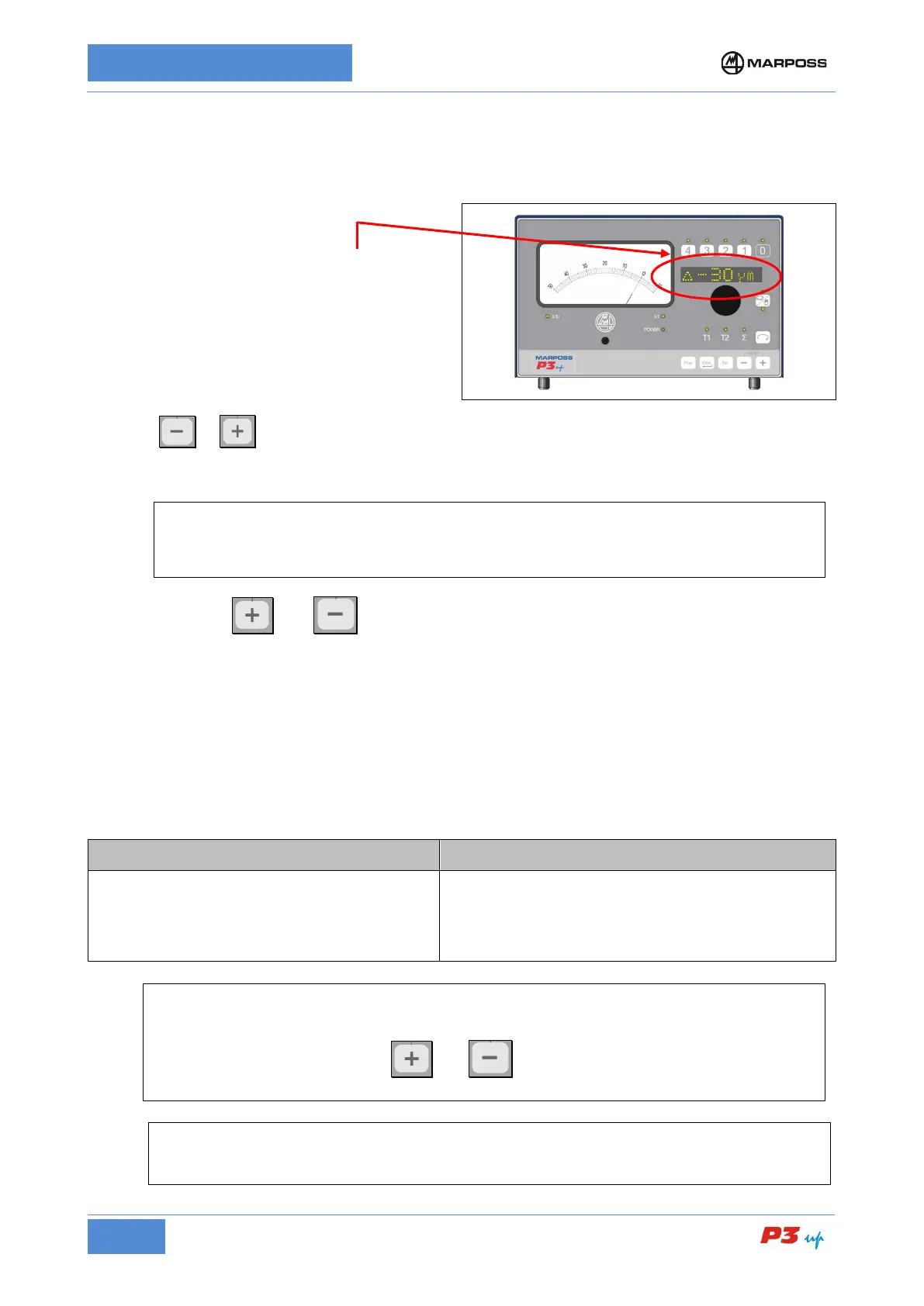
The present of pulse FEEDBACK is indicated by
the “∆” symbol at the left of the alphanumerical
display, followed by the corresponding feedback
value.
Press the or buttons to increase or reduce the value (the correction STEP is set-up as described
in para.
7.3.2.5 FBK STEP). Press and hold the button to increase the value repeatedly by the correction
value.
[
The correction value (+) or (-) may be derived from the machine logic via two dedicated external
signals at the P3UP input (see para. 0
). It is not possible to use the I/O signals for the correction
value when the P3UP is in the alarm condition or manual programming state.
Press and hold the
and buttons simultaneously to zero the FEEDBACK value. The zero is
executed after a short delay in order to prevent the value from being zeroed inadvertently.
The correction logic is as follows:
• correction + => more stock metal is removed => smaller Outside Diameter (O.D.);
larger internal diameter (I.D.).
• correction - => less stock metal is removed => larger Outside Diameter (O.D.);
smaller internal diameter (I.D.).
The correction ranges, which depend on the programmed step value, are as follows:
STEP = 0.2 range = +/- 19.8
STEP = 0.5 range = +/- 19.5
STEP = 1 range = +/- 60
STEP = 2 range = +/- 60
STEP = 0.00001 range = +/- 0.0004
STEP = 0.00002 range = +/- 0.00198
STEP = 0.00004 range = +/- 0.00196
STEP = 0.00008 range = +/- 0.00192
[
When the upper or lower range limit is reached, the feedback value on the alphanumerical display
starts flashing and no further correction values are accepted from the P3UP. The feedback vaue
may only be reset by pressing the
and buttons simultaneously. If the value reaches
the limits, the OVR.FEEDBACK logic output is activated (see para. 6.3).
By activating the “FBK RST” function (see paragraph 7.3.2.6
), the Pulse Feedback value is
zeroed automatically at the end of each InProcess cycle.