Installation and User Manual
46
6.4
Connecting the analogue output
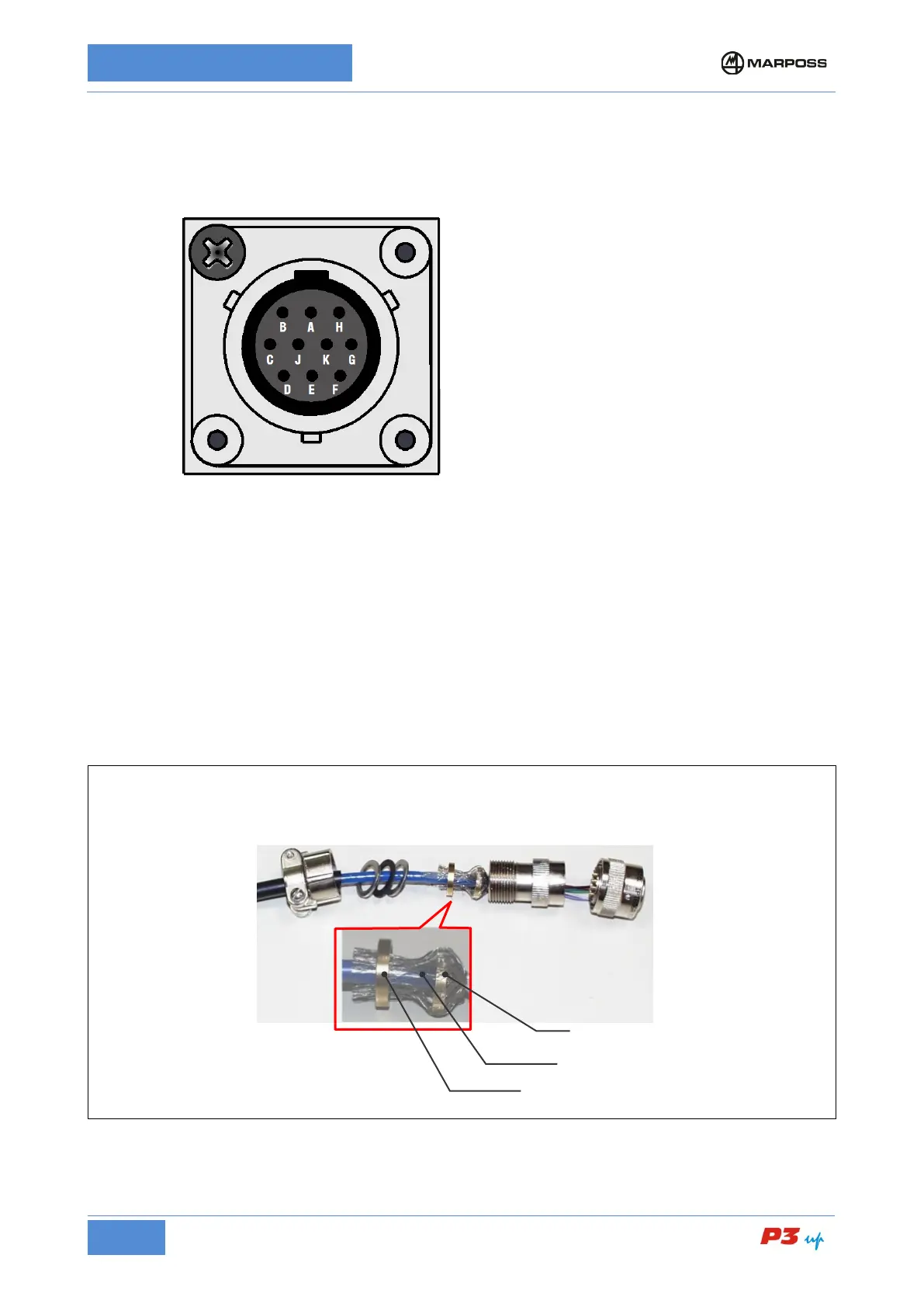
The analogue output is available as an option for the In-Process measurement only. Connect the 10 pin
(female) connector W3 as shown below.
Analogue output voltage: ± 10Vdc
Output resistance: 100 Ω
Maximu permissible load resistance:
≥
10kΩ
Use a globally shielded (max 10 m) cable with the braid connected to the case of the connector (P3UP
connection) and to the machine chassis at the other end by means of suitable terminal block or metallic
cable clamp.
Make sure that the contact surface between the shields and the machine chassis is ample, free from
surface insulation (e.g. paint) and the connections are kept as short as possible.
It is important to guarantee the continuity of the shield even when there are switches and circuit breakers
installed along the line, making sure that the parts that require shielding in the vicinity of the switches are
kept to an absolute minimum.
Use differential inputs for the best measurement results.
Figure 61: Analogue output connection