Installation and User Manual
57
6.7.4
Mechanical zero-setting In-Process heads with WEMAR type support
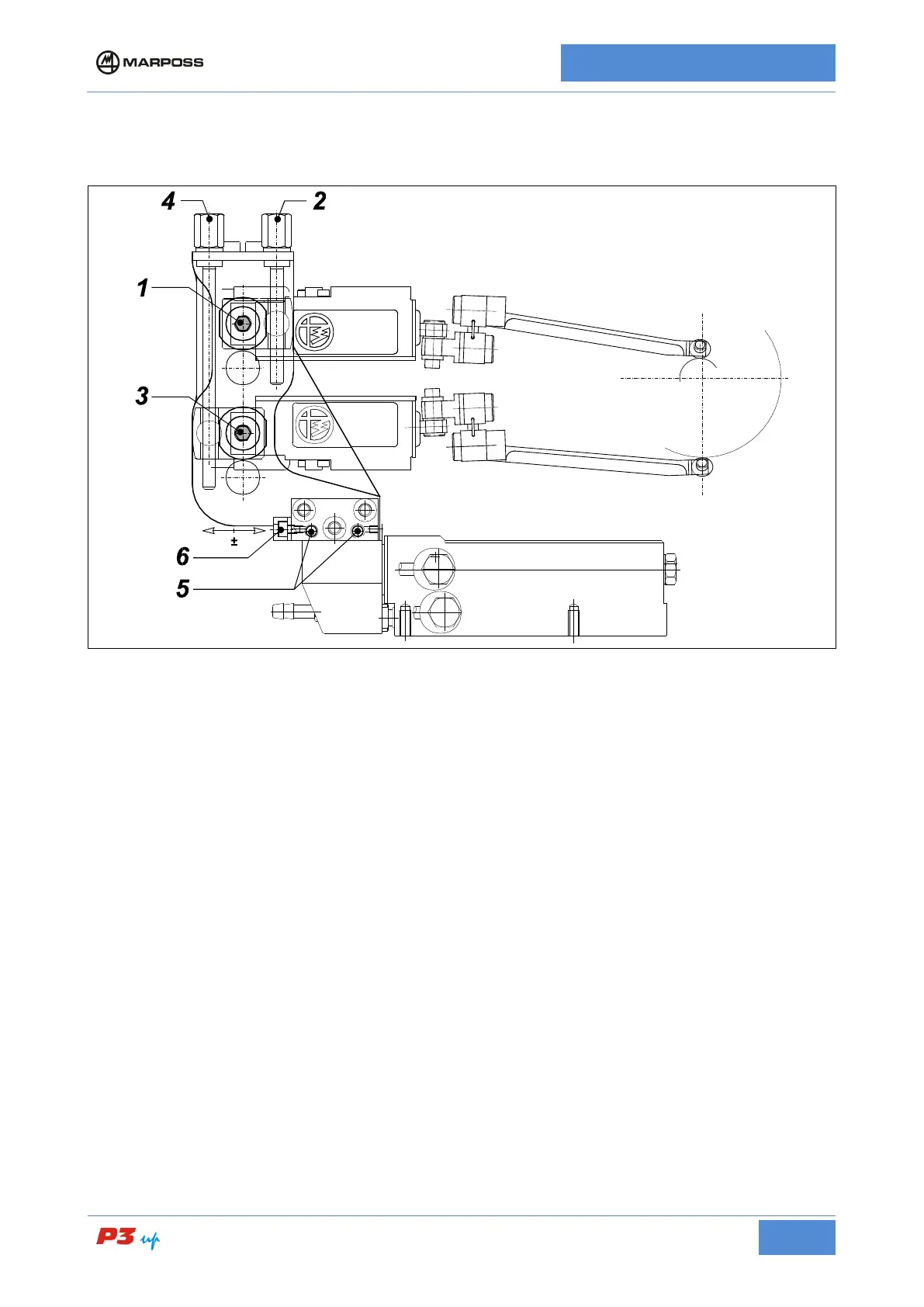
Figure 19: Mechanical zero-setting with WEMAR type support
• Measurement head diameter alignment
(Refer to the layout of Figure 19: Mechanical zero-setting with WEMAR type support)
1. Place a ground workpiece either on the spindle or between the centers.
2. Loosen screws 1 and 3 so as to allow frictioned movement of screws 2 and 4 (fractioned head
movement on support).
3. Rotate screws 2 and 4 in order to move the styli to a position where it is possible to insert the head in
the measurement position in safely (without impact with the workpiece).
4. Move the measurement head to the measurement position.
5. Rotate screws 2 and 4 to so that the contacts are touching the workpiece and are within range (refer to
the readout of the individual transducers on the electronic unit).
6. Tighten screws 1 and 3.
7. Loosen screws 5 maintaining the friction on them.
8. Rotate screw 6 moving the measuring head backwards/forwards until it reaches the position
corresponding to the maximum measurement readout (contacts on diameter); refer to the diameter
display on the electronic unit.
9. Tighten screws 5.
10. Rotate the screw/knob 6 in the opposite direction to release it and avoid tensioning the adjustment
system.