Installation and User Manual
56
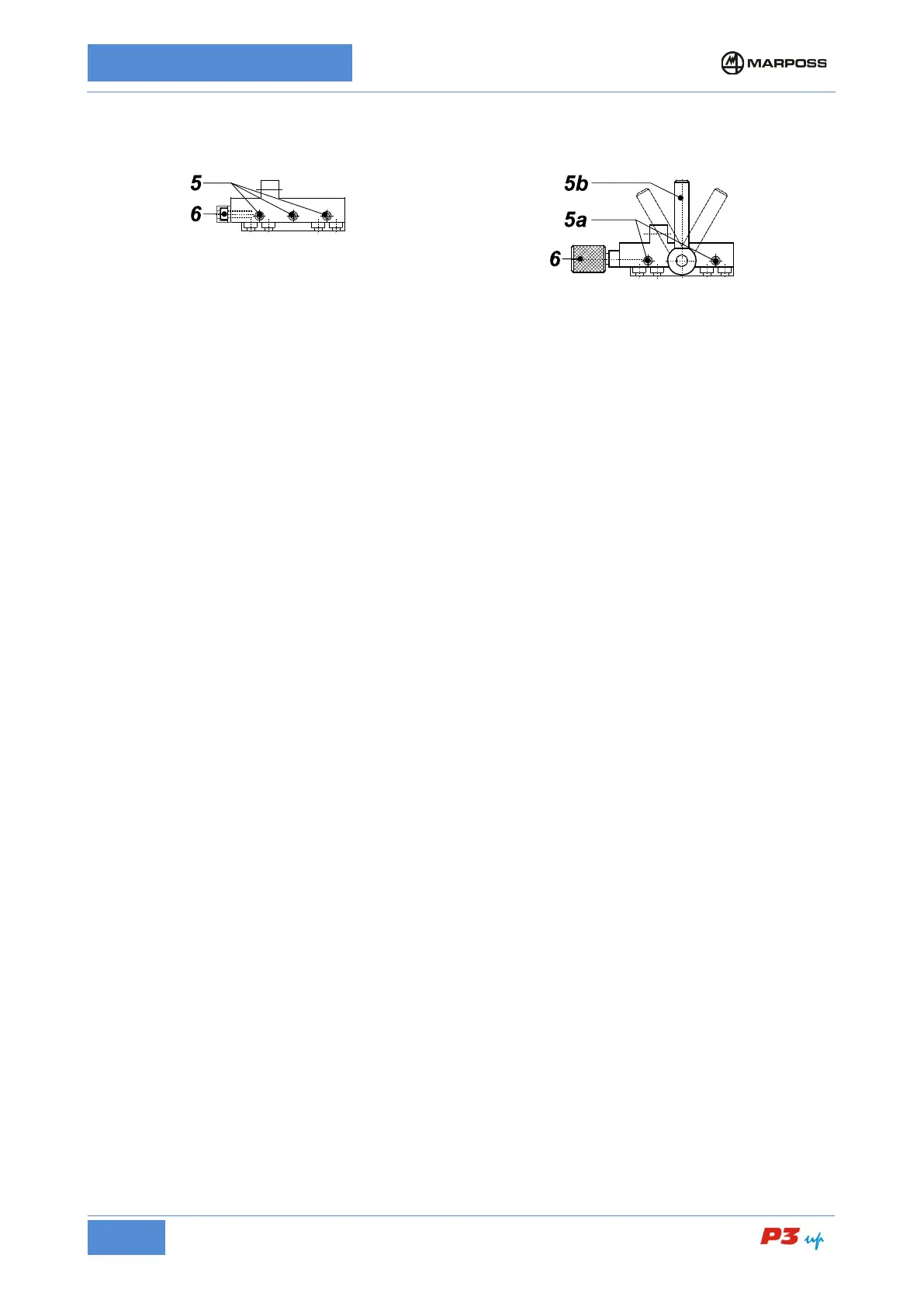
Head support – Slide with
retaining screws
Loosen screws 5 maintaining the friction on them.
Head support – Slide with
locking handle
Release the movement of the head support by
adjusting the handle 5b.
Adjust screws 5a so as to allow frictioned movement of
Rotate the screw/knob 6 moving the measuring head forwards/backwards until it reaches the position
corresponding to the maximum measurement readout (contacts on diameter); refer to the diameter display
on the electronic unit.
Tighten screws 5.
Lock the head support with handle 5b.
Rotate the screw/knob 6 in the opposite direction to release it and avoid tensioning the adjustment system.
• Zero-Setting on Diameter
(Refer to the layout of Figure 18: Fast zero-setting Unimar heads with locking lever)
1. Place a ground workpiece either on the spindle or between the centers.
2. Rotate the locking lever A of the frictioned support to "SET UP", making the movement of heads T1 and
T2 be slightly frictioned.
3. Open the heads to be able to insert them on the workpiece in safe conditions.
4. Bring the heads to measuring position.
5. Simultaneously push levers B on the rapid zero-setting unit present on the stylus holders and close the
heads with a single movement bringing the contacts into contact with the master workpiece.
6. While holding down levers B, rotate lever A to "RUN" until the heads are locked
7. Release the B levers on the rapid zero-setting unit. Make sure that the B levers return to the rest
position and that the contacts T1 and T2 measurement is within ±150 µm (refer to the readout of the
individual transducers on the electronic unit).