Installation and User Manual
39
6.3.3
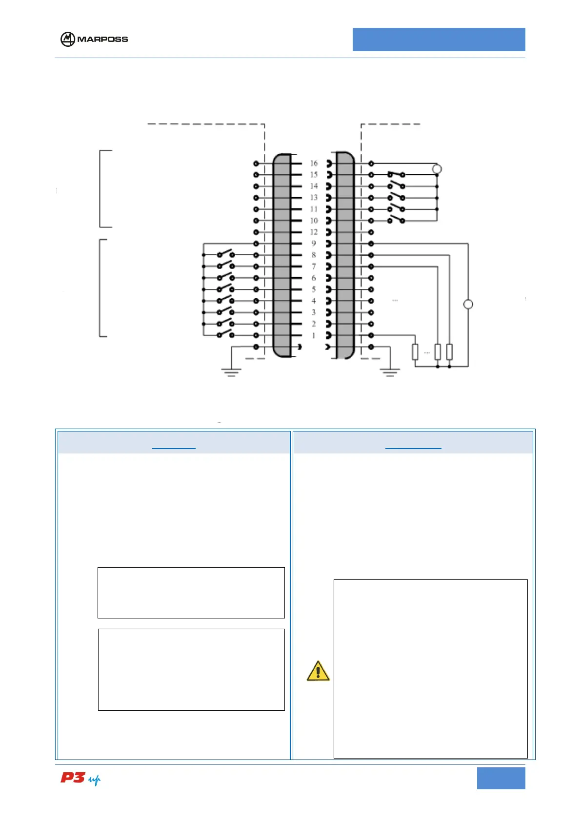
I/O TYPE B – 24V d.c. opto-isolated type machine I/O
H1 connector wiring diagram for I/O TYPE B
INPUTS OUTPUTS
24V d.c., current SINK/SOURCE. The SINK/SOURCE
current connection for the inputs can be selected by
connecting t
he inputs common terminal. Electrical
specifications:
• input active
V
I
(ON) = 15 to 30 V d.c
I
I
(ON) = 10 mA (V
I
= 24 V d.c), 6 to 12 mA (V
I
= 15 to 30 V d.c)
• Input deactivated
V
I
(OFF) = (−3 to 5) V d.c.,
N.B.
The SINK current type inputs connection
features specifications that are compatible
with the "TYPE 1" digital inputs as defined in
the Standard EN61131-2.
[
N.B.:
The “SINK current” input is driven by a switch
or limit switch connected between the input
itself and the positive pole of the mach
ine I/O
power supply. The SOURCE input is driven
by a switch or limit switch connected between
the input itself and the negative pole of the
machine I/O power supply.
24Vd.c. / 10 mA, current SOURCE/SINK seletable via
output common connections:
• output active
I
O
(ON) = 10 mA tip. (max 13 mA) with resistive
load
V
O
dropout (ON) = 3 V tip. (min 2.2 V / max
3.4 V)
• output deactivated
V
O
(OFF) = max 30V d.c.
I
O, PARAS
(OFF) = max 200 µA (parasitic current in
deactivated state)
The outputs are
fitted with a short duration short
circuit protection: max 0.5 s; install a protection
device capable of limiting the current at each
output to less than 100 mA in the event of a
fault. For example, each individual input may be
fitted with:
• A quick-blow, non-
rating of 50-70 mA;
• A resettable, 450-
handle a current of at least 100 mA(*).
In this case it is important to pay special
attention to the signal level, since the voltage
drop across the fuse is summed with the
dropout at the outp
ut. In the worst case
scenario, when using SOURCE current output
INPUTS COMMON
START CYCLE
OUTPUTS COMMON
C4
**
OVR FEEDBACK *
C4 **
C3
C2
C1
C0
N.B.
* available in some configurations only
**according to the configurations
User’s logic (ex.CNC, PLC, etc.)