Installation and User Manual
35
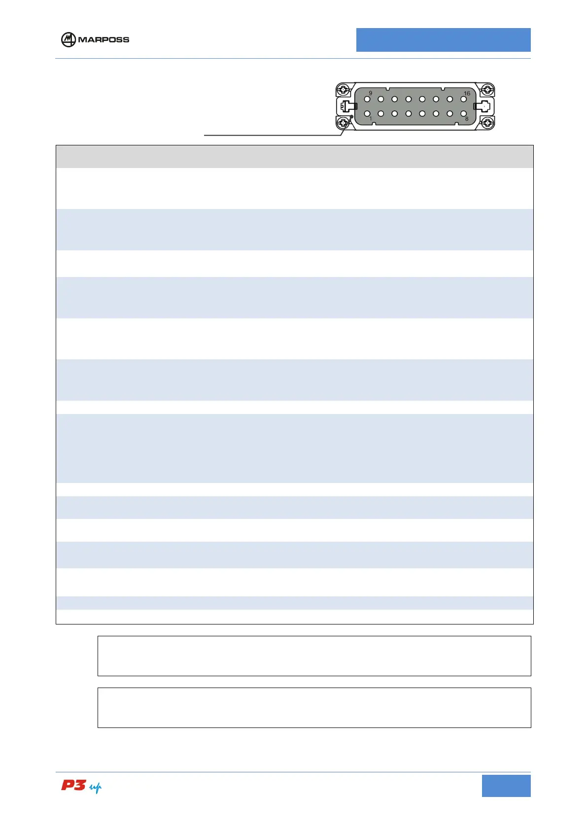
I/O signal connections
SIGNAL I/O DESCRIPTION
16
INPUT COMMON
In
The input circuits drive voltage supply must be applied between this
terminal (inputs common) and each individual terminal in use (via a
micro-switch or similar device).
15
-START CYCLE
In
The Start Cycle signal is connected to this terminal Remove the
power supply to this terminal to enable measurement system during
working cycle.
14
MEMORY
CONTROL
In
The update memory signal is connected to this terminal; it is used
when there is an analogue memory card installed on the system.
13
HEAD
RETRACTION
In
The retraction signal is connected to this terminal; it is used when the
measurement heads retraction circuit is installed. Connect the power
supply to this terminal to retract the measurement heads.
11
PULSE
FEEDBACK +
In
The positive correction signal (pulse feedback +) is connected to
this terminal If included it can be used to supply the correction value
via an input signal.
10
PULSE
FEEDBACK -
In
The negative correction signal (pulse feedback -) is connected to
this terminal If included it can be used to supply the correction value
via an input signal.
n.c.
9
OUTPUTS
COMMON
Out
The output signals can be monitored by connecting the external
loads (relays or other compatible input devices) between one pole of
the power supply and each individual terminal in use. The other pole
of the power supply must be connected to this terminal (outputs
common).
The zero command (C0) signal is connected to this terminal.
2
C1
Out
The first command (C1) signal is connected to this terminal; the first
command may be replaced by other functions.
3
C2
Out
The second command (C2) signal is connected to this terminal; the
second command may be replaced by other functions.
4
C3
Out
The third command (C3) signal is connected to this terminal; the third
command may be replaced by other functions.
6
OVR FEEDBACK
Out
The maximum correction value reached signal is connected to this
terminal, if included.
The automatic signal is connected to this terminal.
7
+24 Vnst
There is an unstabilised 24 V d.c. voltage present on this terminal.
[
N.B.
For a list the functions present on your model, consult the I/O list supplied with the unit.
[
N.B.
Some pins may not be present, depending on the specific model.