Installation and User Manual
61
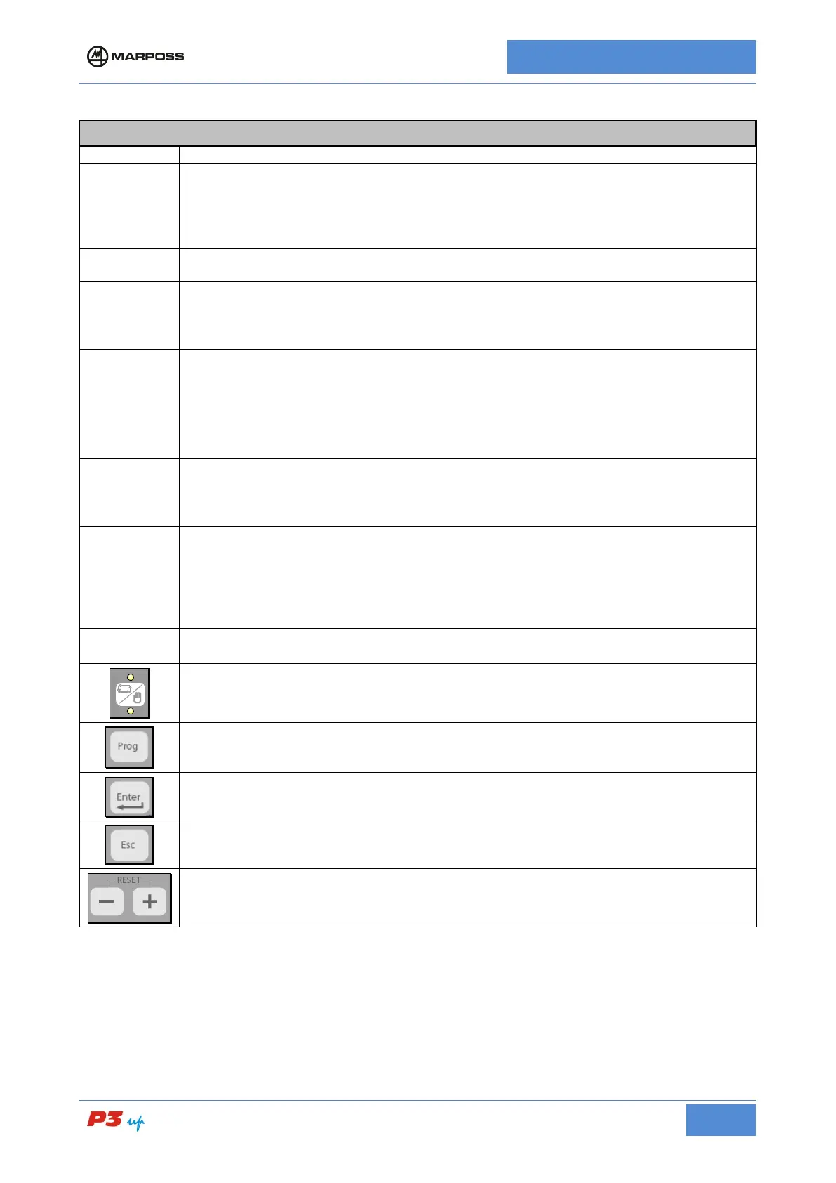
Tabella 71: Description of the P3UP panel
1
Analogue measurement display instrument. The following types are available:
• 50-0-10 (x1 / x10) μm White
• 100-0-20 (x1 / x10) μm White
• 10-0-2 (x1 / x10) μm White
• 50-0-10 (x1 / x10) μm / inch Yellow
2
Grinder advance control points setting buttons and in-process command trigger indicator
LEDs.
3
8 character digital alphanumerical display. This is used to display:
• Alarms
• Zero Adjust/Pulse Feedback Values
4
█ (green) = device switched on;
N.B. If a memory card is installed, the green LED indicates that the memory is not processing the
measurement.
█ (blue) = Indicates that the memory is operating
N.B. For an explanation of how the LED functions, see para. 0
█ (red) = alarm condition
5
KNOB (press and rotate); it can be used to:
• Scroll through the alarm list
• Scroll through the programming menu
• Set-up the zero correction value (Zero Adjust)
6
Button with lamps that indicate when the following transducers and measurements are
selected:
• T1: In-Process measurement head transducer 1 selected
• T2: In-Process measurement head transducer 2 selected
• Σ: In-Process cycle measurement selected
• Dyn: Surface and stock metal estimate memory activated
7
Analogue measurement display instrument mechanical zero setting see Ref. 1 (Fitted with
protective cap) see para. 7.1
Automatic or manual operating mode selector button. The LEDs indicate which operating
mode has been selected. The LED flashes during the measurement cycle.
Press this button to access the programming menu. See para.7.3.1. for detailed description
Press this button to confirm your selection.
Press this button to close the selected operation.
Pulse feedback buttons (see para.7.2.5); these buttons may also be used to
program parameter values. (See para.7.3)