Installation and User Manual
54
• Measurement head diameter alignment
(Refer to the examples in Figure 16: Measurement head with two probes and Figure 17: UNIMAR
Measurement Heads)
1. Place a ground workpiece in the spindle or between the tips.
2. Loosen screws 1 and 3 to allow a frictioned movement of the contact tips 2 and 4.
3. Rotate contact tips 2 and 4 moving them to a position where it is possible to insert the head in the
measurement position in safely (without impacting the part).
4. Move the measurement head to the measurement position.
5. Rotate contact tips 2 and 4 so that the contacts touch the workpiece and are within their range (refer to
the display of individual transducers on the electronic unit).
6. Tighten screws 1 and 3.
7. Now adjust the head support unit.
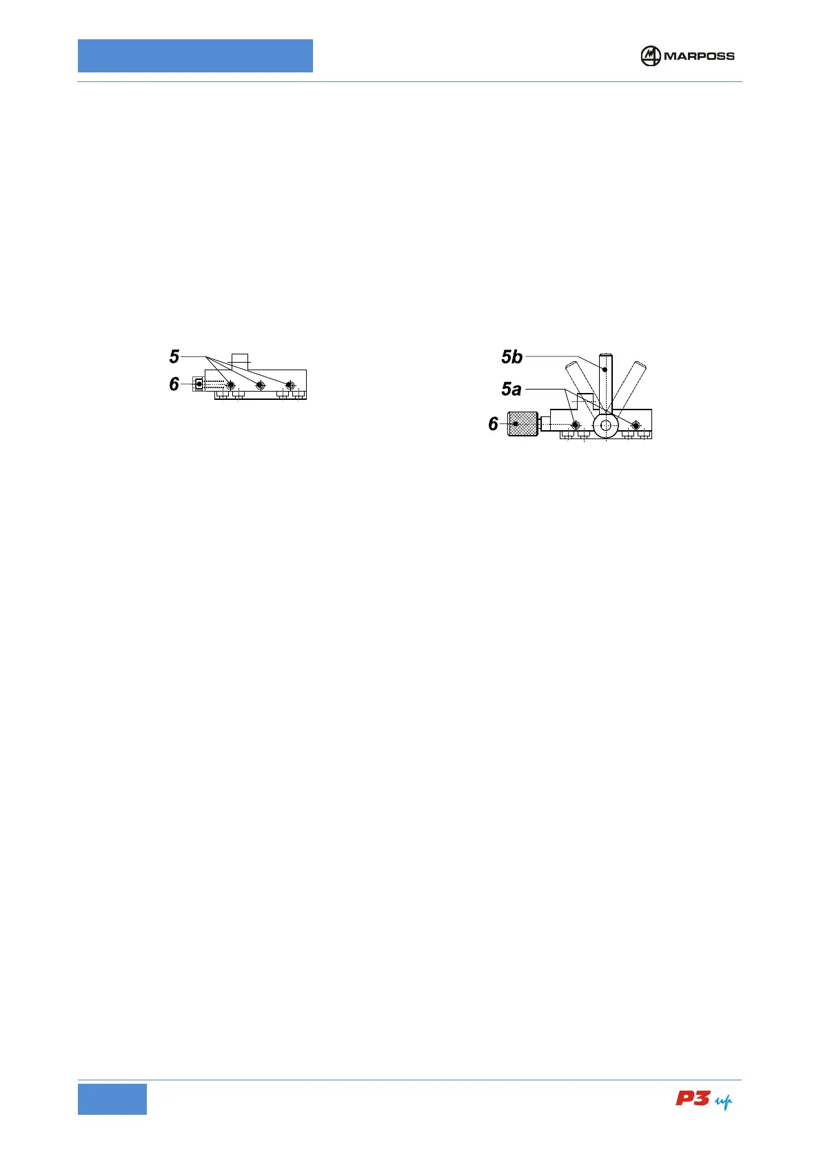
Head support – Slide with
retaining screws
Loosen screws 5 maintaining the friction on them.
Head support – Slide with
locking handle
Release the movement of the head support by
adjusting the handle 5b.
Adjust screws 5a so as to allow frictioned movement of
Rotate the screw/knob 6 moving the measuring head forwards/backwards until it reaches the position
corresponding to the maximum measurement readout (contacts on diameter); refer to the diameter display
on the electronic unit.
Tighten screws 5.
Lock the head support with handle 5b.
Rotate the screw/knob 6 in the opposite direction to release it and avoid tensioning the adjustment system.
• Adjusting the Upper Contact
(Refer to the examples in Figure 16: Measurement head with two probes and Figure 17: UNIMAR
Measurement Heads)
1. Loosen screw 1 maintaining the friction on it.
2. Rotate the latch 2 so that the upper contact touches the master workpiece and the measurement value
that appears on the gauge is around zero (± 10 µm).
3. Tighten screw 1 after completing these operations.
• Adjusting the Lower Contact
(Refer to the examples in Figure 16: Measurement head with two probes and Figure 17: UNIMAR
Measurement Heads)
1. Loosen screw 3 maintaining the friction on it.
2. Rotate the latch 4 so that the lower contact touches the master workpiece and the measurement value
that appears on the gauge is around zero (± 10 µm).
3. Tighten screw 3 after completing these operations.