272 CONTENTS
3. Connect all input lines of all cameras together.
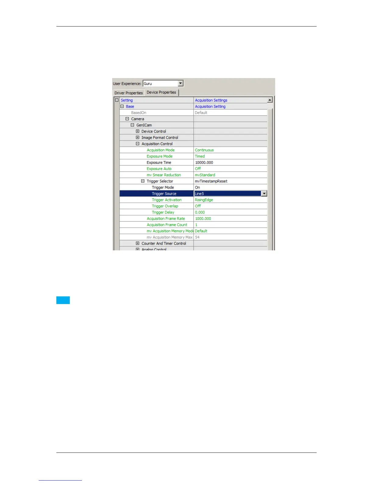
4. Finally, use one output of one camera to generate reset edge:
Figure 1: wxPropView - Setting the sample
Note
Be aware of the drift of the individual timestamps.
The timestamp is generated via FPGA in the camera which itself is clocked by a crystal oscillator. This
is done independently in each camera and by default not synchronized among cameras or the host system.
Typical stability of crystal oscillators is in the range 100ppm (parts per million).
I.e. for longer operation times (say in excess of hours) there is a tendency that timestamps of individual
cameras drift against each other and against the time in the operating system of the host.
Customers wishing to use the individual camera timestamps for synchronization and identification of im-
ages via timestamps for multi-camera systems will have in the meantime
- to reset all timestamps either by hardware signal or by command and regularly resynchronize or check the
drift algorithmically
- in order to make sure that the drift is less half an image frame time.
MATRIX VISION GmbH