6.3 European Union Declaration of Conformity statement 23
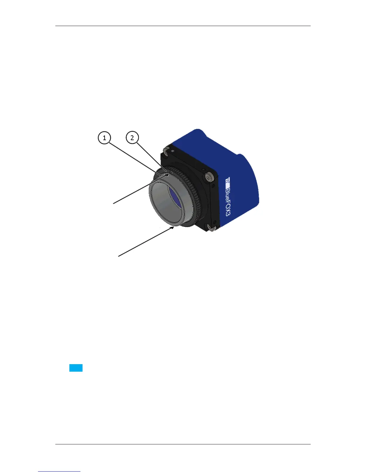
6.2.8 Adjusting the C-mount (mvBlueFOX3-2xxx-2xxx)
The mvBlueFOX3-2xxx-2xxx cameras allow a precise adjustment of the back focus of the C-mount by means of a
back focus ring which is threaded into the C-mount and is secured by a lock nut ring which itself is secured by two
screws. The mechanical adjustment of the imaging device is important in order to achieve a perfect alignment with
the focal point of the lens. This adjustment is made before leaving the factory to conform to the standard of 17.526
mm (in air) and should normally not require adjustment in the field. However, if the back focal plane of your lens
does not conform to the C-mount back focus specification or if you have e.g. removed the IR-CUT filter (p. 72),
renewed adjustment may be required.
Figure 2: mvBlueFOX3-2xxx-2xxx Lensholder with C-mount ring (1) and lock nut ring (2)
How to proceed:
• Loosen screws (location as shown above by arrows) of the lock nut ring with an Allen key (0.9 x 50).
• Loosen the lock nut ring.
• With the lens set to infinity or a known focus distance, set the camera to view an object located at "infinity" or
the known distance.
• Rotate the C-mount ring and lens forward or backwards on its thread until the object is in sharp focus.
Note
Be careful that the lens remains seated in the C-mount.
• Once focus is achieved, tighten the lock nut ring, then tighten the two locking screws of the lock ring without
applying excessive torque.
6.3 European Union Declaration of Conformity statement
MATRIX VISION GmbH