9.1 Dimensions 57
Warning
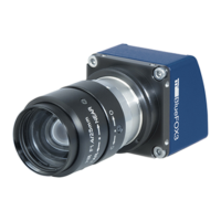
Since the connector of the I/O board will also fit upside down, you have to be careful while connecting.
Otherwise you can destroy the camera and / or the I/O board. As show in the figure, if the I/O board was
connected correctly, you can bend the I/O board on the back of the sensor board. Then the I/O board connector
will point to the opposite direction as the sensor.
Figure 10: mvBlueFOX3-M connected I/O board
The pinning of the mvBlueFOX3-I/O is described in the chapter Circular connector male (Power / Digital I/O)
(p. 59).
Note
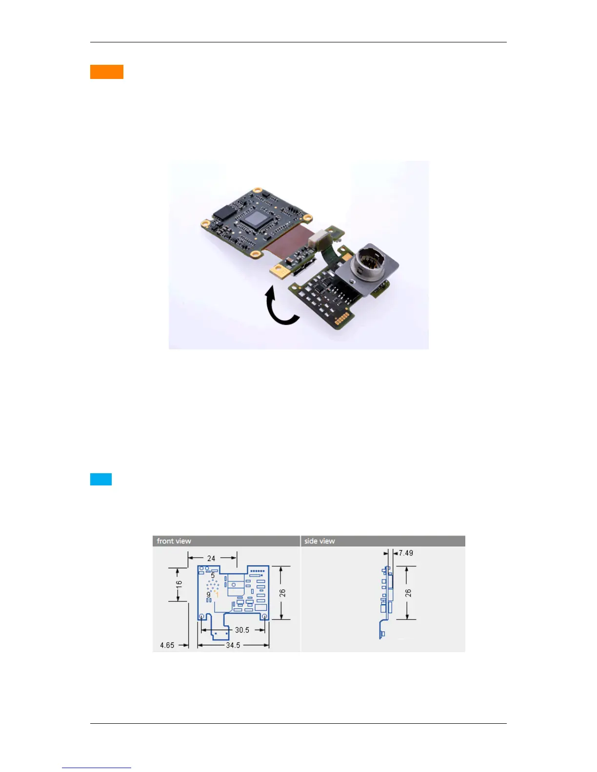
There is also a version of the I/O board without connector as "mvBlueFOX3-IO NC" (NC = not connected).
The pinning is provided in the figure:
Figure 11: mvBlueFOX3-M dimensions of additional I/O board without connector.
MATRIX VISION GmbH