MT7620 PROGRAMMING GUIDE
Integrated 802.11n MAC/BBP and 2.4 GHz RF/FEM Router-on-a-Chip
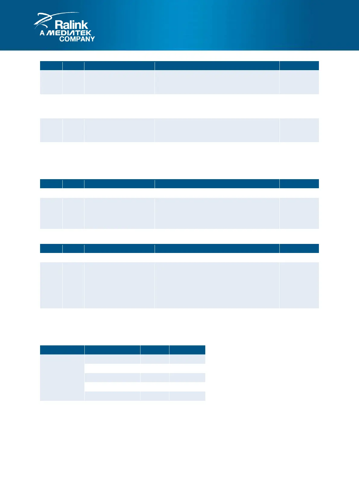
Trailing Edge Ring Indicator
Indicates when the RIN (Ring Indicator) pin
changes from a low to a high value.
Delta Data Set Ready
Indicates when the DSRN (Data Set Ready) pin
changes.
Delta Clear to Send
Indicates when the CTSN (Clear to Send) pin
changes.
NOTE:
0: False
1: True
55. SCRATCH: Scratch Register (offset: 0x0024)
Scratch
This register is defined as a scratch register in
16550 application. It has no hardware function,
and is retained for compatibility only.
56. DL: Clock Divider Divisor Latch (offset: 0x0028)
Divisor Latch
This register is used in the clock divider to
generate the baud clock.
The baud rate (transfer rate in bits per second)
is defined as:
baud rate = 40 MHz / (CLKDIV * 16).
NOTE:
1. In standard 16550 implementation, this register is accessible as two 8-bit halves only. In this implementation,
the DL register is accessible as a single 16-bit entity only.
2. DL[15:0] should be >= 4.
 Loading...