9 - 6 VM600 MPS hardware manual (standard version) MAMPS-HW/E
Edition 17 - February 2018
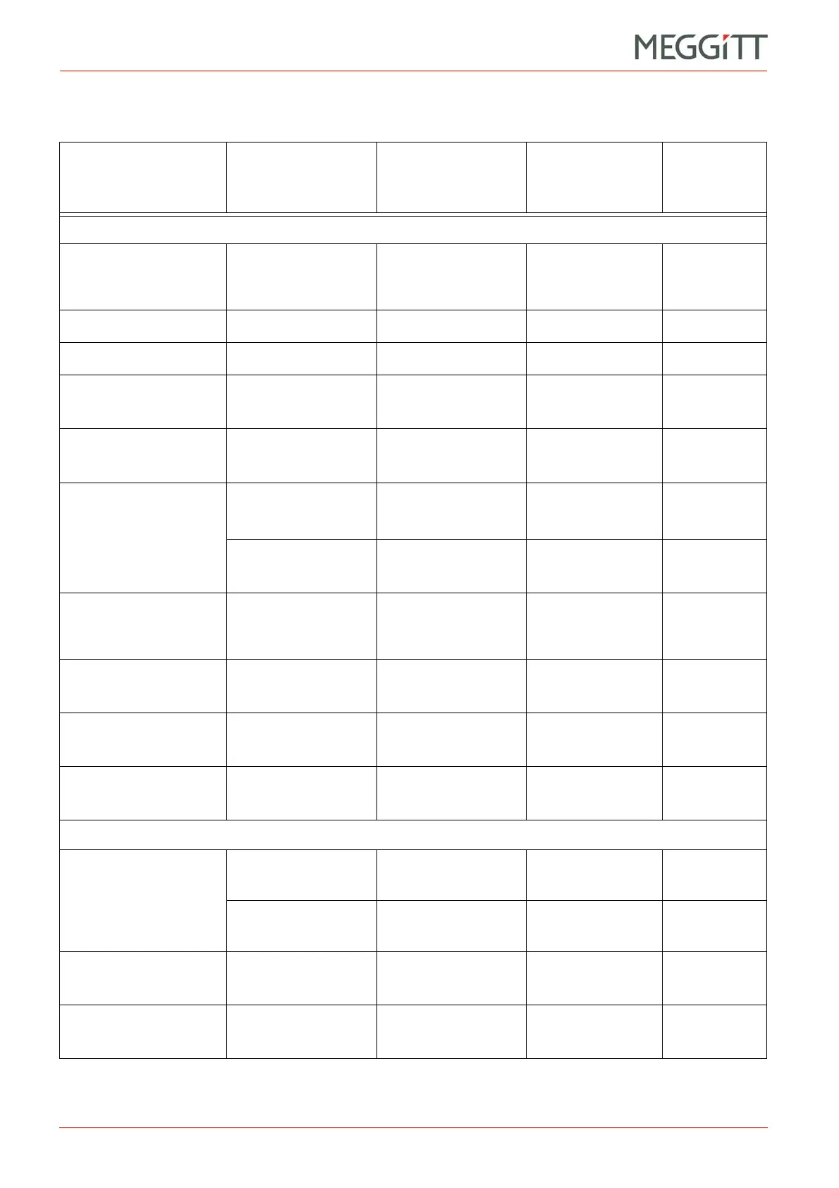
Connecting vibration and pressure sensors
CONFIGURATION OF MPC4 / IOC4T CARDS
Table 9-2: Use of an internal (MPC4) or external power supply for various types of sensors
Transducer or
transducer and
signal conditioner
Output signal Rating Supplied by
Connection
diagram
Accelerometers and velocity transducers
2-wire constant current
power supply (CE680
or competitor product)
1Vto20V
2to20mA
(18 to 30 V
DC
)
MPC4 / IOC4T Figure 9-6
CE1xx and CE3xx 5 mA ±2 mA
12 to 18 V
DC
MPC4 / IOC4T Figure 9-5
SE120 12mA±8mA
+15 to +36 V
DC
MPC4 / IOC4T Figure 9-5
CAxxx + IPC704
(2-wire, current mode)
12 mA
DC
/ 5 mA
AC
+18to30V
DC,
25 mA
MPC4 / IOC4T Figure 9-5
CAxxx + IPC704
(3-wire, voltage mode)
+7.5 V
DC
/ 5 V
AC
+18to30V
DC,
25 mA
MPC4 / IOC4T Figure 9-4
CV210 + IVC632
Current modulation:
12 mA ±5 mA
15 to 30 V
DC
I
max
17 mA
MPC4 / IOC4T Figure 9-5
Voltage modulation:
7.5 V
DC
±5 V
AC
I
max
6mA
MPC4 / IOC4T Figure 9-4
Velocity transducers
such as CV210 or
competitor product
AC only N/A N/A Figure 9-7
CAxxx + IPCxxx
with GSI127
7V
DC
±5 V
AC
+24 V
DC
±10%,
100 mA
External supply Figure 9-8
CAxxx + IPCxxx
with GSI124
7V
DC
±5 V
AC
+24 V
DC
±10%,
60 mA
External supply Figure 9-9
CExxx with GSI124
7V
DC
±2 V
AC
+24 V
DC
±10%,
60 mA
External supply Figure 9-9
Displacement probes
TQ4xx + IQS45x
Voltage output:
0to20 V
20 to 32 V MPC4 / IOC4T Figure 9-4
Current output:
15 to 20 mA
25 mA max. MPC4 / IOC4T Figure 9-5
TQxxx + IQSxxx
with GSI127
Voltage output:
0to20 V
24 V
DC
±10%,
125 mA
External supply Figure 9-8
TQxxx + IQSxxx
with GSI124
Voltage output:
0to20 V
24 V
DC
±10%,
85 mA
External supply Figure 9-9
 Loading...


