10 - 18 VM600 MPS hardware manual (standard version) MAMPS-HW/E
Edition 17 - February 2018
Assigning alarm signals to relays on the RLC16 card
CONFIGURATION OF AMC8 / IOC8T CARDS
10.8.1.1 Configuration procedure (OC Bus)
To configure a particular relay on the RLC16 card using the OC Bus, proceed as follows:
1- Consult Table 10-2 (this lists the jumpers associated with each relay).
2- For the relay in question, set the appropriate jumper on the RLC16 card.
3- Set the appropriate jumper to configure the relay as normally energised (NE) or normally
de-energised (NDE).
NOTE: Make sure that either the NE or the NDE jumper is set. You cannot set both of them
together.
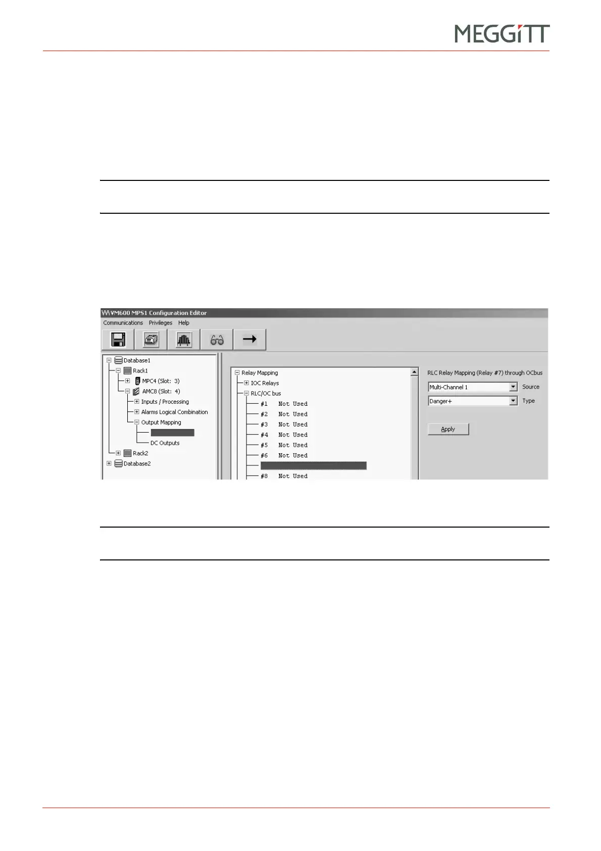
4- Using the VM600 MPSx software, select the Discrete Outputs node (a child of the
Output Mapping node) in the tree structure (left). Then expand the RLC/OC bus node
in the main window (right) and select the relay in question (between 1 and 16). See
Figure 10-13.
5- Configure the Source and Type fields of this window.
NOTE: Refer to the relevant manual for further information: VM600 MPS1 software
manual or VM600 MPS2 software manual.
Configuration example
A user wants to assign the alarm signal “Danger+" generated on Multi-Channel 1 of a given
AMC8 card to Relay 7 on the RLC16 card. In addition, the user wants Relay 7 to be in a
normally energised (NE) state.
Relay 7 is selected by placing jumper J31 on the RLC16 card (see Table 10-2).
(Note that this operation actually selects OC Bus Line 6. This information, however, does not
normally concern the user, as the VM600 MPS software takes it into account.)
Placing jumper J88 will ensure that Relay 7 is normally energised (see Table 10-2).
The user must then use the VM600 MPSx software to select Relay 7 from the 16 relays
available in the RLC/OC bus node. Then, the Danger+ alarm for Multi-Channel 1 can be
assigned to this relay (see Figure 10-13).
Figure 10-13: VM600 MPS software window to configure the OC Bus
 Loading...


