VM600 MPS hardware manual (standard version) MAMPS-HW/E 10 - 23
Edition 17 - February 2018
Assigning alarm signals to relays on the RLC16 card
CONFIGURATION OF AMC8 / IOC8T CARDS
Placing jumper J88 will ensure that Relay 7 is normally energised (see Table 10-2).
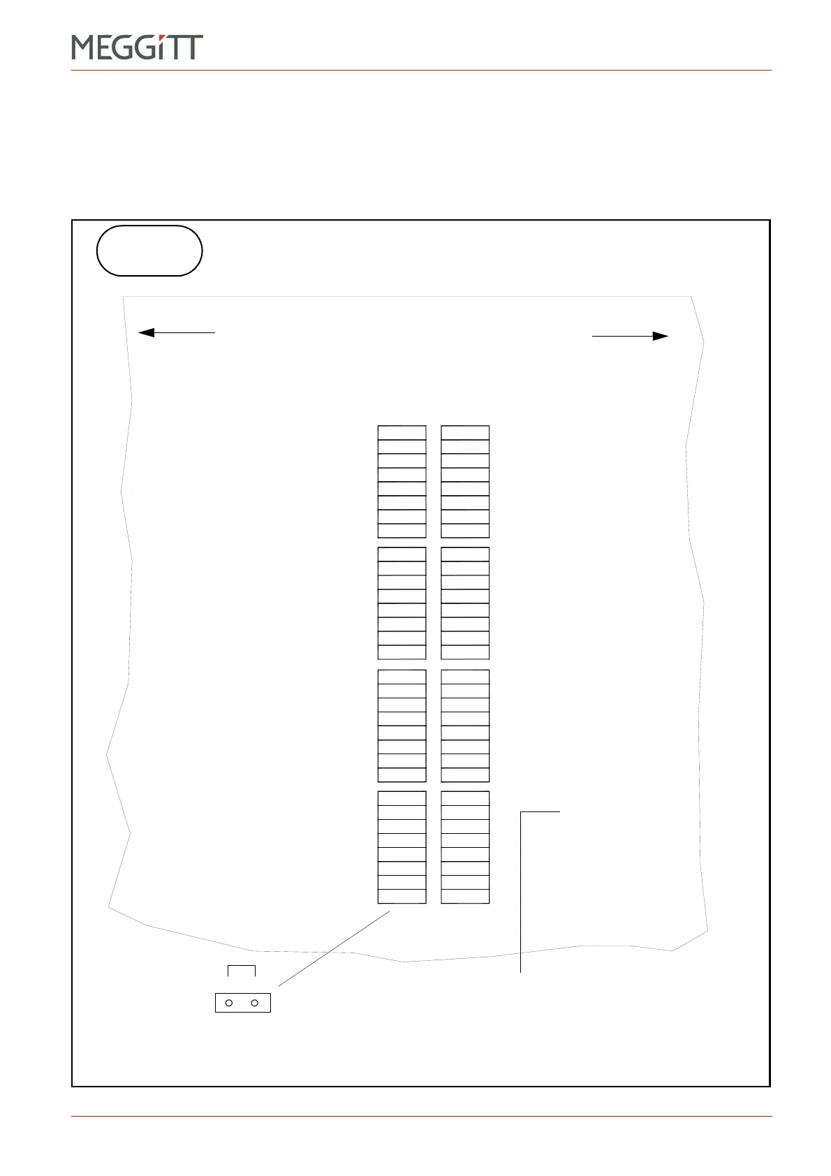
Jumper J138 now has to be set on the IOC8T card.
The user must then use the VM600 MPSx software to select Relay 7 from the 16 relays
available in the RLC/Raw bus node. Then, the Danger+ alarm for Multi-Channel 1 can be
assigned to this relay (see Figure 10-17).
J101
J103
J105
J107
J109
J111
J113
J115
J117
J119
J121
J123
J125
J127
J129
J131
1
2
3
4
5
6
7
8
9
10
11
12
13
14
15
J133
J135
J137
J139
J141
J143
J145
J147
J149
J151
J153
J155
J157
J159
J161
J163
J100
J102
J104
J106
J108
J110
J112
J114
J116
J118
J120
J122
J124
J126
J128
J130
J132
J134
J136
J138
J140
J142
J144
J146
J148
J150
J152
J154
J156
J158
J160
J162
0
17
18
19
20
21
22
23
24
25
26
27
28
29
30
31
16
1
3
5
7
9
11
13
15
2
4
6
8
10
12
14
16
1
3
5
7
9
11
13
15
2
4
6
8
10
12
14
16
1
3
5
7
9
11
13
15
2
4
6
8
10
12
14
16
1
3
5
7
9
11
13
15
2
4
6
8
10
12
14
16
12
Figure 10-18: Position of jumpers on the IOC8T card related to the Raw Bus lines
(Top of card, component side)
(Bottom of card)
Raw Bus
line pairs
Relay
number
IOC8T
Raw Bus line pairs are indicated.
For example:
Raw Bus line 25 high (H) = jumper J150
Raw Bus line 25 low (L) = jumper J151
Raw Bus
“high”
Raw Bus
“low”
To J1
To P3
 Loading...


