10 - 22 VM600 MPS hardware manual (standard version) MAMPS-HW/E
Edition 17 - February 2018
Assigning alarm signals to relays on the RLC16 card
CONFIGURATION OF AMC8 / IOC8T CARDS
10.8.2.1 Configuration procedure (Raw Bus)
To configure a particular relay on the RLC16 card using the Raw Bus, proceed as follows:
1- Consult Table 10-2 (this lists the Raw Bus lines and jumpers associated with each relay).
2- Choose a free Raw Bus line from the four that are associated with that relay.
3- For the relay and Raw Bus line in question, set the appropriate jumper on the RLC16
card.
4- Set the appropriate jumper on the RLC16 card to configure the relay as normally
energised (NE) or normally de-energised (NDE).
NOTE: Make sure that either the NE or the NDE jumper is set. You cannot set both of them
together.
5- For the relay and Raw Bus line in question, set the appropriate jumper on the IOC8T
card.
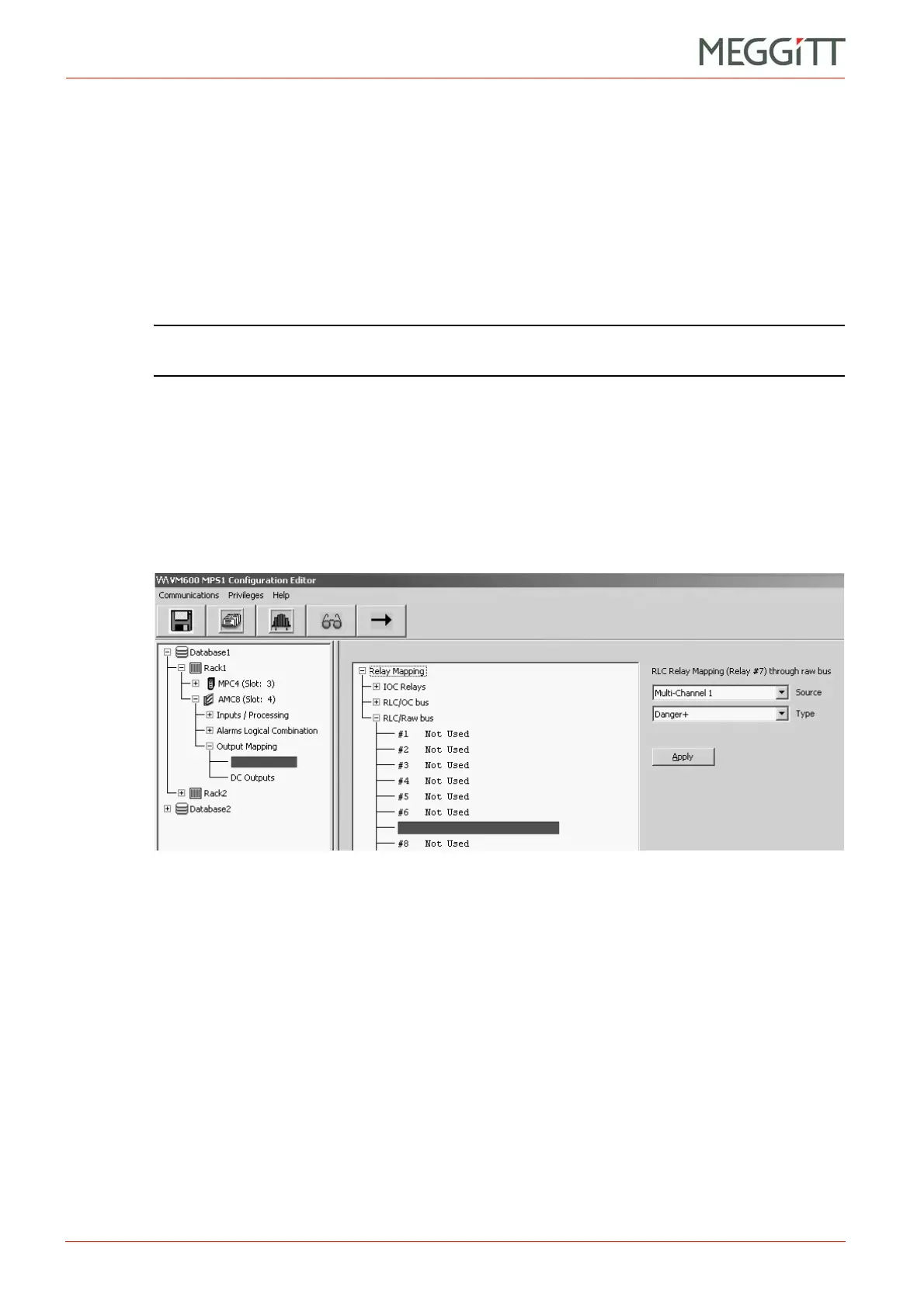
6- Using the VM600 MPSx software, select the Discrete Outputs node (a child of the
Output Mapping node) in the tree structure (left). Then expand the RLC/Raw bus node
in the main window (right) and select the relay in question (between 1 and 16).
See Figure 10-17.
7- Configure the Source and Type fields of this window.
Configuration example
A user wants to assign the alarm signal “Danger+" generated on Multi-Channel 1 of a given
AMC8 card to Relay 7 on the RLC16 card. In addition, the user wants Relay 7 to be in a
normally-energised (NE) state.
Table 10-2 shows that Raw Bus lines 35, 43, 51 and 59 are associated with Relay 7.
The choice of one of these four lines will be dictated by the hardware configuration of the
overall MPS, as certain bus lines may already be reserved for other functions. The desired
bus line is then selected by placing the appropriate jumper on the RLC16 card (J32, J33, J34
or J35 in the case of Relay 7).
For the sake of this example, we will assume that Raw Bus line 51 is chosen. Jumper J34
therefore has to be set on the RLC16 card.
Figure 10-17: VM600 MPS software window to configure the Raw Bus
 Loading...


