VM600 MPS hardware manual (standard version) MAMPS-HW/E 10 - 21
Edition 17 - February 2018
Assigning alarm signals to relays on the RLC16 card
CONFIGURATION OF AMC8 / IOC8T CARDS
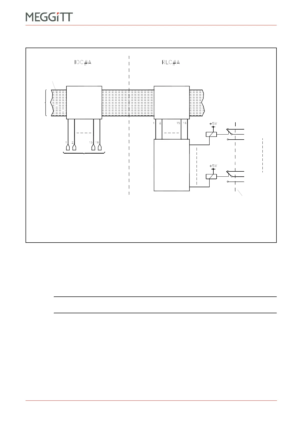
Figure 10-16 shows the operating principle when the Raw Bus is used to switch relays.
The attribution of a specific alarm signal (generated by the AMC8 / IOC8T cards) to a control
signal line is done using the VM600 MPSx software.
These alarm signals include Alert, Danger, Global Channel OK Fail, AMC Configuration Not
Running, Status Latched. During normal operation (that is, when no alarms/problems
present) the corresponding control signals are low. They become high when an alarm or other
problem is detected.
NOTE: Refer to the relevant manual for further information: VM600 MPS1 software
manual or VM600 MPS2 software manual.
The attribution of a specific control signal line to a specific Raw Bus line is done by setting a
jumper on the IOC8T card. The jumper settings are summarised in Table 10-2 and the
position of the relevant jumpers on the IOC8T card is shown in Figure 10-18.
The control signal is subsequently routed towards a specific relay on the RLC16 card by
setting a jumper on the RLC16. Additional jumpers on the RLC16 allow the selection of relay
normally energised (NE) or normally de-energised (NDE). The jumper settings are
summarised in Table 10-2 and the position of the relevant jumpers on the RLC16 card is
shown in Figure 10-19.
The IOC8T card drives the Raw Bus lines using open collector driver circuitry. These bus
lines do not have line terminations. (The principle is the same as for the Open Collector Bus,
see Figure 3-7.)
Figure 10-16: Using the Raw Bus to switch relays
Relay 1
Relay 16
RLC16
panel
Jumpers
to select
NE/NDE
Jumper
matrix
(on RLC16)
Control
signals
(see note 1)
Raw
Bus
Notes
1. Specific alarms (A+, D and so on) generated by the corresponding AMC8 card are
attributed to the control lines using the VM600 MPSx software. The control signals are
low during normal operation (in the absence of an alarm or other problem).
Jumper
matrix
(on IOC)
64 lines
 Loading...


