© Microhard Systems Inc. 20
3.0 Hardware Description
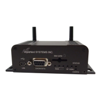
3.1.2 Connectors and Indicators
3.1.2.1 Front
On the front of the IPn3G is the USB port, DIAGNOSTIC port, CONFIG Button, RSSI, STATUS, RF and
SGNL LED’s as described below:
The USB port can be used for: (See Section 4.1.7 USB Configuration)
Console Port
Data Mode
NDIS Mode
The Diagnostic port (RS232) is used for:
AT Command Interface at 115.2kbps and
HyperTerminal (or equivalent).
User data (RS232 - RxD, TxD, and SG)
Digital I/O—Input Pin 7, Output Pin 8
CONFIG (Button) - Holding this button depressed while powering-up the IPn3G will boot the unit into
FLASH FILE SYSTEM RECOVERY mode. The default IP address for system recovery (only - not for nor-
mal access to the unit) is static: 192.168.1.39.
If the unit has been powered-up for some time (>1 minute), depressing the CFG Button for 8 seconds will
result in FACTORY DEFAULTS being restored, including a static IP address of 192.168.0.1. This IP ad-
dress is useable in a Web Browser for accessing the Web User Interface.
RF LED (Red) - When connected to a 2G/EDGE or 3G-WCDMA Network, the RF LED indicates
a transmission burst. When connected to a 3G/HSPA Network the LED has no function.
SGNL LED (Green) - When illuminated, the SGNL LED indicates that the modem is connected and syn-
chronized with a wireless carrier.
Receive Signal Strength Indicator (RSSI) (3x Green) - As the received signal strength increases,
starting with the furthest left, the number of active RSSI LEDs increases. If the measured signal strength is
less than –110dBm no LED’s will be illuminated. If the signal is greater than –105dBm, 1 LED will be on, -
100dBm equals 2 LED’s, and any signal greater than –95dBm will show all 3 RSSI LED’s to be ON.
STATUS LED (Red) - Upon initial application of power the STATUS LED will be illuminated for approxi-
mately 20 seconds, after which time it will being to blink slowly (loading) for an additional 25 seconds, then
stay ON ‗solid‘ (indicating it has achieved its specific operational status).
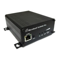
Drawing 3-4: IPn3G Front View
Signal
Name
PIN
#
Input or
Output
RXD 2 O
TXD 3 I
SG 5
Digital In 7 I
Digital Out 8 O
Table 3-1: Diagnostic Port RS232 Pin Assignment
Windows USB driver
downloads are available
to registered users
from:
microhardcorp.com/
support
microhard SYSTEMS INC.
SIM CARD
RSSI
DIAGNOSTIC
RF SGNL
STATUS
CONFIG
USB
Digital I/O is only
available and has been
implemented on units
shipped after June 1,
2012