© Microhard Systems Inc. 81
4.0 WebUI Configuration
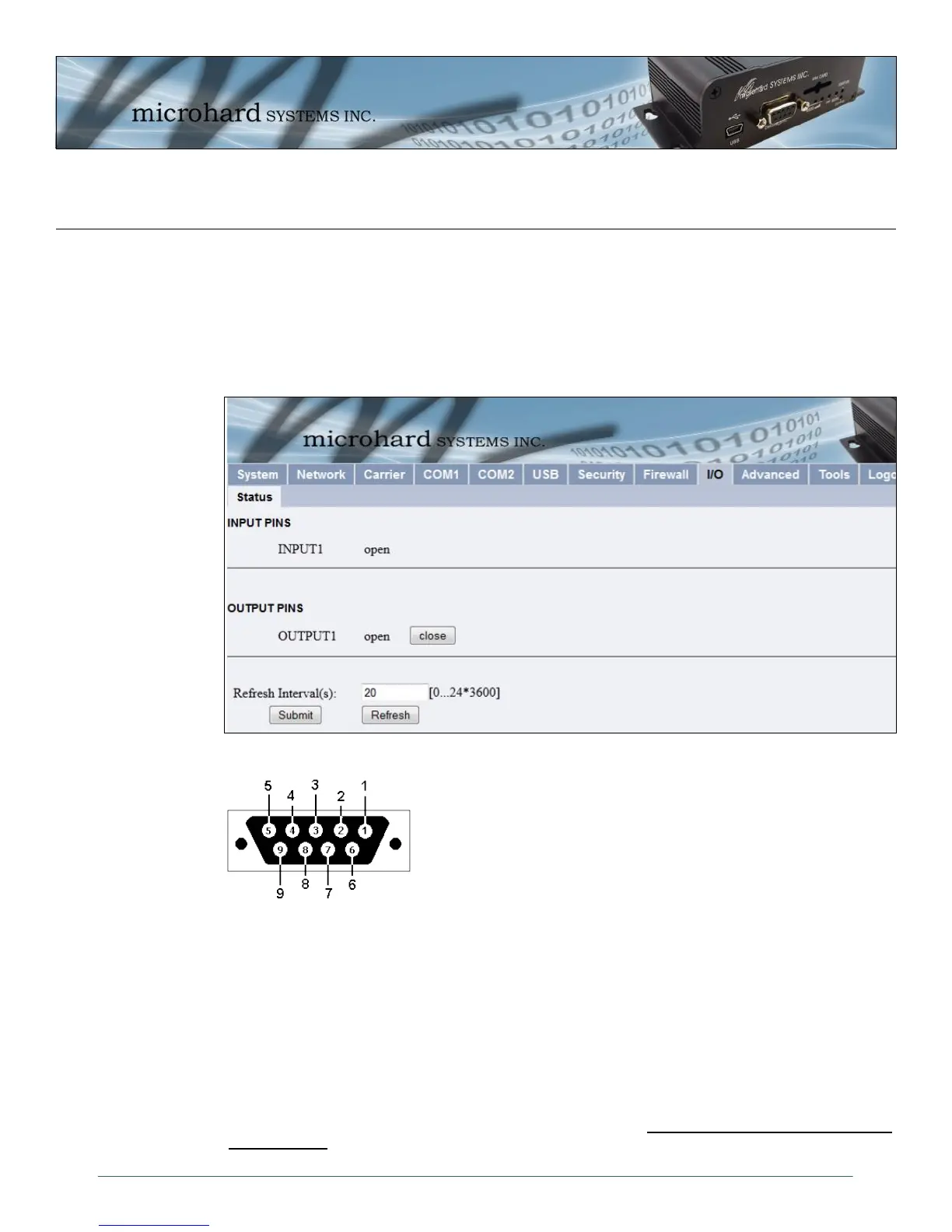
Image 4-44: I/O > Status
4.9 I/O
4.9.1 Status
On the front diagnostics (COM2) port of the IPn3G (Units shipped after June 1, 2012), 2 pins have been
set aside to be used for Digital I/O. Pin 7 is used as an INPUT, and Pin 8, is used for an OUTPUT. The
status window shows the current status of these pins.
INPUT PINS
Pin 7 on the Diagnostics port of the IPn3G can be used to detect an input. Pin 7 has a small wetting
current (Vin) used to detect a contact closure, and prevent false readings by any noise or intermittent
signals, it has a threshold sensitivity of 1.8V.
OUTPUT PINS
Pin 8 on the diagnostics port of the IPn3G can be used to provide an output signal, which can be used, for
example, to drive an external relay to control an external device. Appendix G: Digital I/O: Driving an
External Relay, provides a example schematic of how this would work. Maximum recommended load for
the Output Pin is 150mA @ 32 VDC (Vin)
Diagnostics Port (DB9 - Female)
Pin 7 - INPUT
Pin 8 - OUTPUT
Image 4-45: I/O > Pin Location