© Microhard Systems Inc. 51
4.0 WebUI Configuration
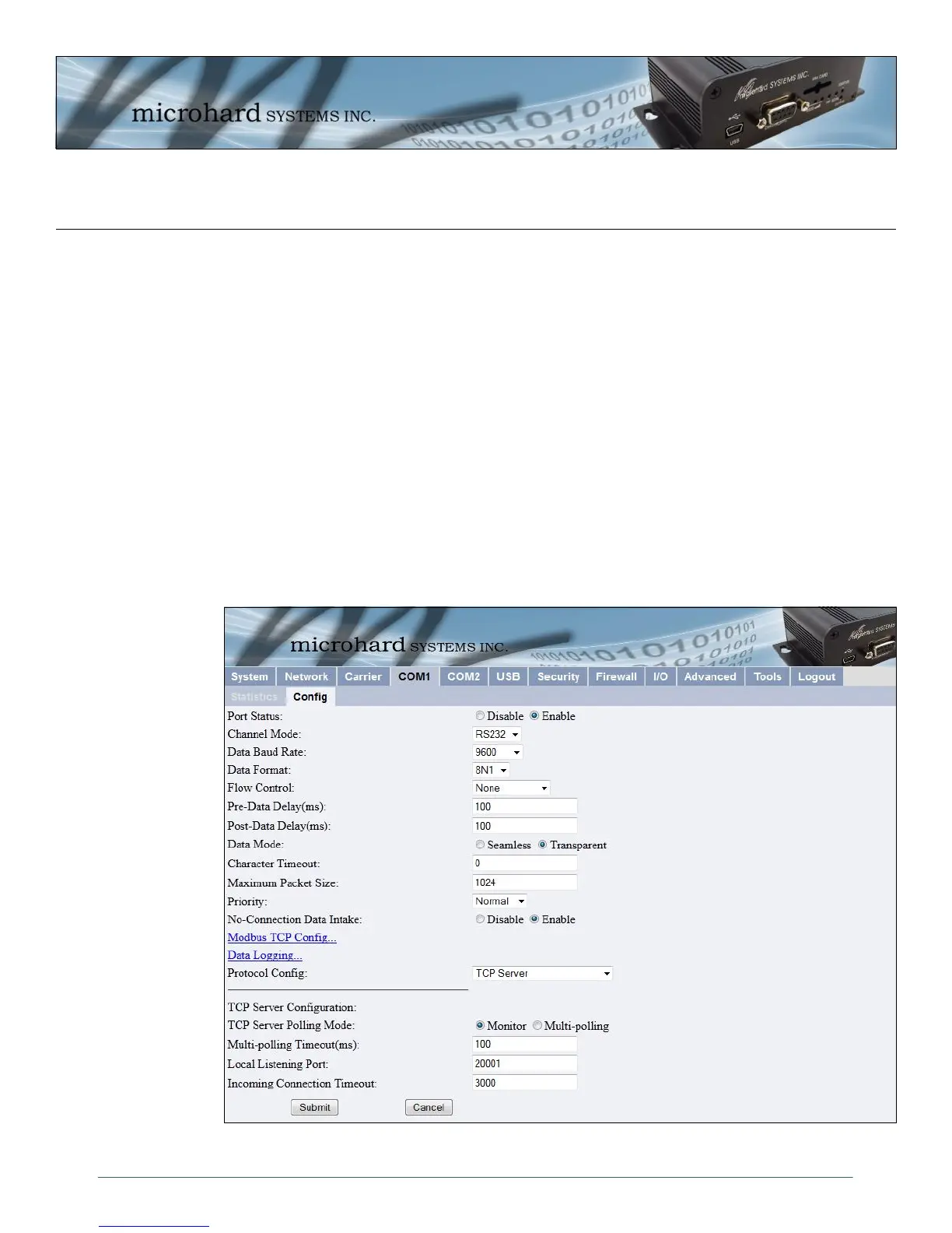
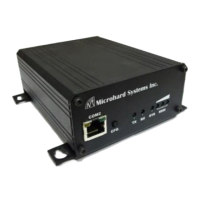
4.5.2 COM1 and COM2 Configuration
The menus ’COM1 > Config’ and ’COM2 > Config’ are used to configure the serial device server for the
serial communications ports:
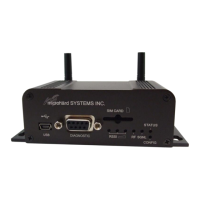
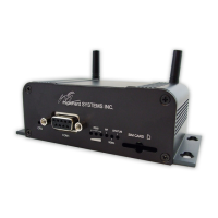
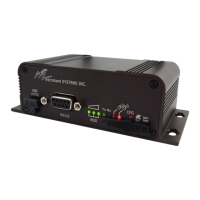
COM1 (DATA), the rear DE9 connector on the IPn3G, and
COM2 (DIAGNOSTIC), the front DE9 connector.
Serial device data may be brought into a LAN network through TCP, UDP, or multicast; it may also exit the
IPn3G network on another IPn3G ’s serial port. Ensure that the firewall allows access to the assigned ports
by either creating rules to allow it, or by setting the WAN Request to allow.
COM1 is a full-featured RS232 interface dedicated to serial data traffic. It supports hardware handshaking.
By default, this port is enabled.
COM2 is, by default, disabled. In this state, it may be used as the console port for the text user interface.
Enabled, it becomes another serial port for data traffic. It is a 3-wire (TxD, RxD, and SG) interface and
does not support hardware handshaking.
For brevity, only COM1 is fully detailed in this section; the relative limitations of COM2 are noted where
applicable.
Image 4-24: COM1 Configuration Menu