• Software Package Management
Description
How to Connect PowerTip LCD to a Parallel Port
Data signals are connected that way:
DB25m Signal LCD Panel
1 Enable (Strobe) 6
2 Data 0 7
3 Data 1 8
4 Data 2 9
5 Data 3 10
6 Data 4 11
7 Data 5 12
8 Data 6 13
9 Data 7 14
14 Register Select 4
18-25, GND Ground 1, 5, 16
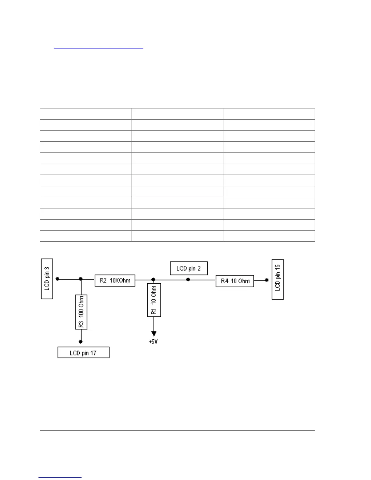
Powering:
As there are only 16 pins for the PC1602 modules, you need not connect power to the 17th pin.
GND and +5V can be taken from computer's internal power supply (use black wire for GND and
red wire for +5V)
WARNING! Be very careful connecting power supply. We do not recommend using external
power supplies. In no event shall MikroTik liable for any hardware damages.
Note that there are some PowerTip PC2404A modules that have different pin-out. Compare:
Page 572 of 695
Copyright 1999-2007, MikroTik. All rights reserved. Mikrotik, RouterOS and RouterBOARD are trademarks of Mikrotikls SIA.
Other trademarks and registred trademarks mentioned herein are properties of their respective owners.
 Loading...