ZS3 Service Manual Page 145 of 295
Figure 14.10-ZS3
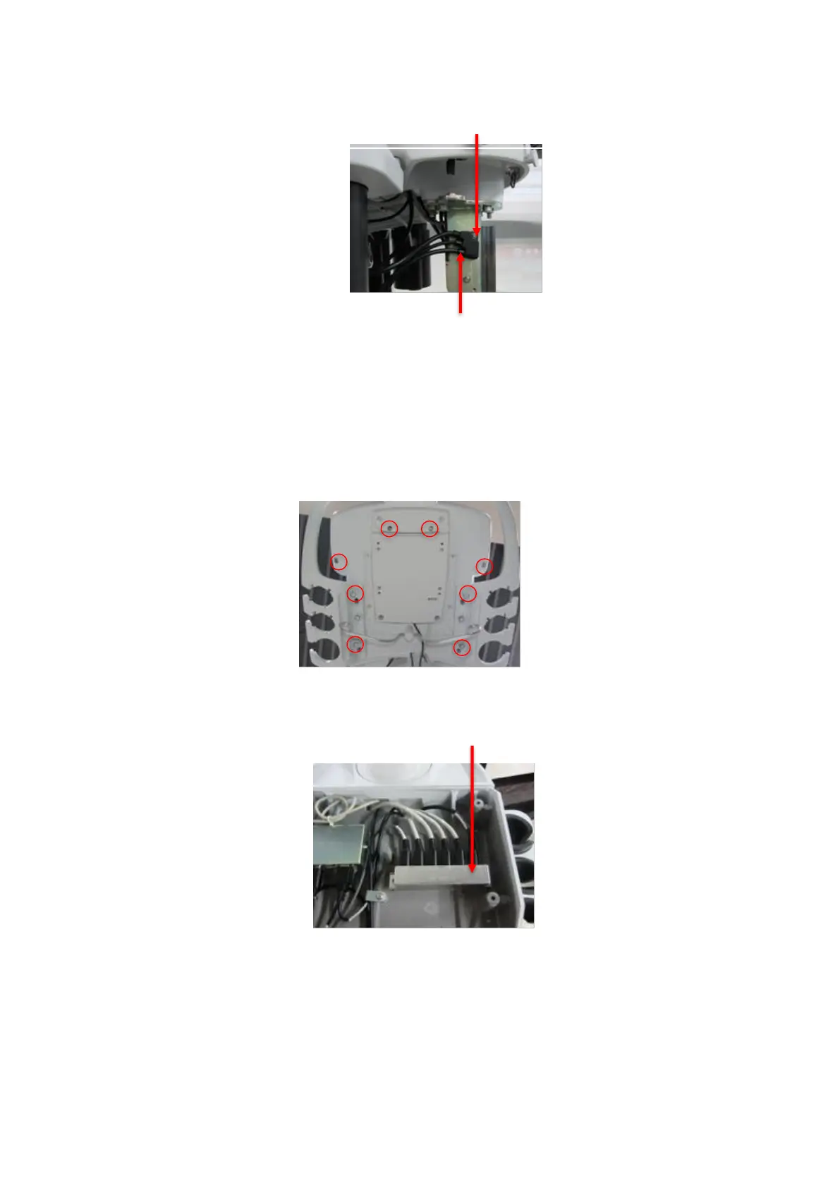
3. Disassemble the eight(8) screws and the UI, Thread the Gel warmer cable
through the punch hole of UI interface base and connect 4-pin connector side into
the rightmost port of the power distribution strip
Figure 14.11-ZS3
Figure 14.12-ZS3
4. Wind a circle and Tie the tail of the Gel Warmer cable and printer USB cable. (If
printer with no options)
Disassemble the eight (8) screws
and the UI
Gel warmer cable connect port
 Loading...