ZS3 Service Manual Page 227 of 295
10. Taking weight off the display, slide it off the threaded studs on the metal hinge
assy.
11. Set the display aside.
Installation:
1. Reconnect the display cables to the connector on the display.
2. Slide the excess cable under the plastics and route in the same fashion prior to
removal.
3. Align the display (4 threaded shafts) with the metal hinge.
4. Reinstall the 9/32” nuts and tighten. Ensure that the display cable is not
pinched.
5. Reinstall the larger display cover by tightening the six (6) Phillips-head screws.
6. Reinsert the smaller display hinge plastic cover –
Insert the bottom piece first, aligning the screw holes and secure the cable.
Slide the top cover down.
7. Tighten the four (4) Phillips-head screws that are retaining the plastic display
hinge back cover.
System Verification:
1. Reconnect the main AC power cord from the rear of the system or plug into the
wall source.
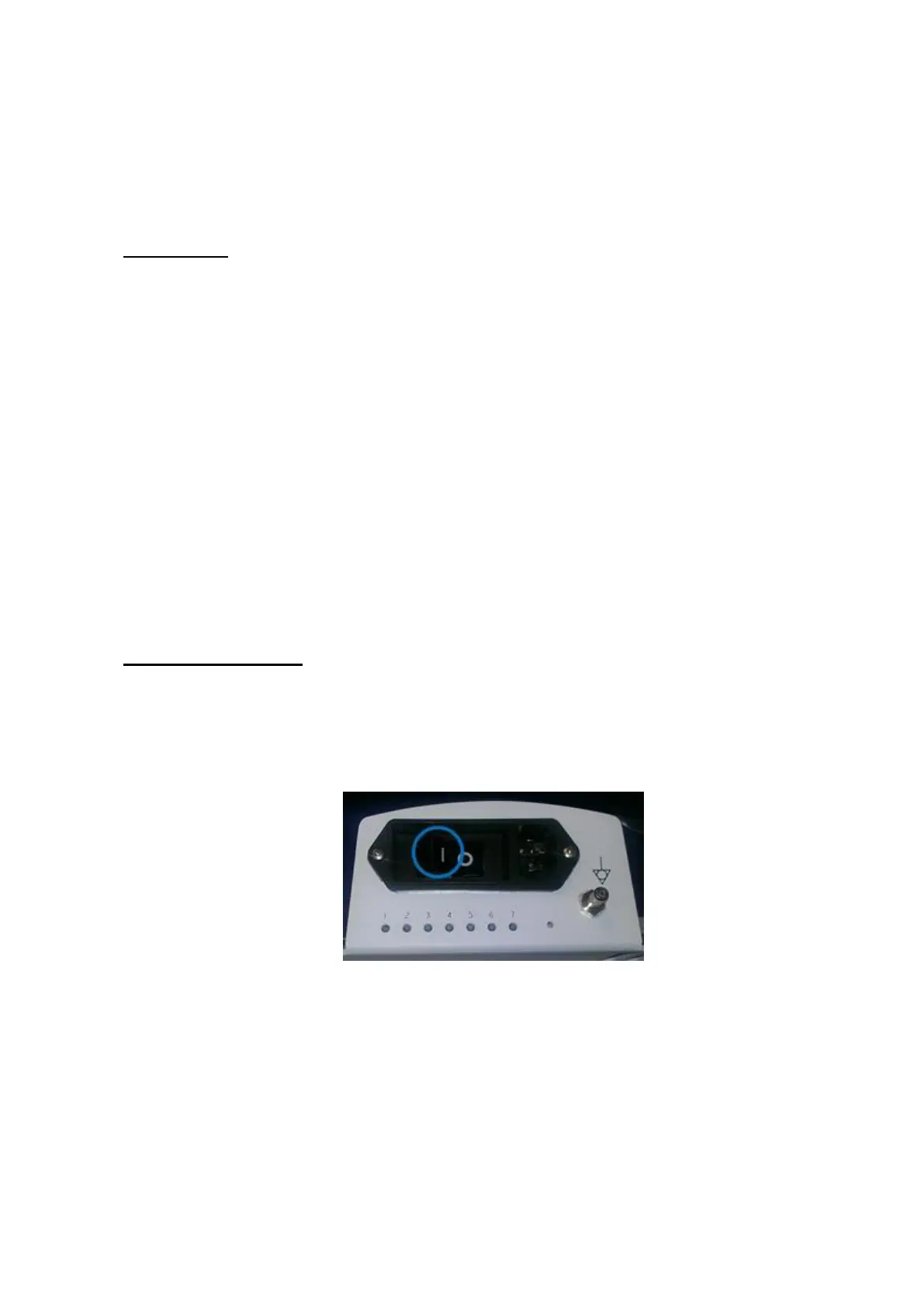
2. Place AC circuit breaker, located at the rear of the system, in the “1” (On)
position.
Figure 19.13-ZS3
3. Ensure the system is docked in the cart.
4. Turn the system on.
5. Verify that the LCD display is functioning correctly by watching the boot
sequence and verifying that normal imaging is displayed after system has fully
booted.
6. Attach a transducer (if not already connected) and enable PW mode.
 Loading...