4 Device installation
4.1 General information
Before starting work, please read Chapter 2 and follow all instructions.
Note:
For use in UL-regulated applications:
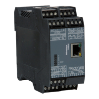
The PR 5220 transmitter must be installed in an NTRL end-enclosure.
WARNING
Warning of a hazard area and/or risk of personal injury
All cable connections must be protected against damage.
Note:
- Measurement cables should be kept away from power equipment.
- Signal cables and measurement cables should be installed separately from electric
power lines.
- It is recommended to lay measurement cables in separate cable conduits.
- Data cables should be crossed at right angles.
Further procedures:
- Check the consignment: make sure that all components are present.
- Safety check: inspect all components for damage.
- Make sure that the on-site installation is correct and complete including cables, e.g.
power cable fuse protection, load cells, junction box, data cables, console/cabinet,
etc.
- Follow all device installation instructions related to application, safety, ventilation,
sealing and environmental inuences.
- Connect the cable from the junction box or platform/load cell.
- If applicable: connect other data cables, power cables, etc.
- Connect to power supply.
- Check the installation.
4.2 Mechanical preparation
4.2.1 Control cabinet units
Have all required parts, technical documents and tools at hand for installation.
Other procedures:
- Install device.
- Secure the cable at the place of installation; e.g.,using cable ties.
Transmitter Series PR 5220 4 Device installation
Minebea Intec EN-24
 Loading...