- Remove the insulation from the cable ends and keep the strands short.
- Connect the screens to the screen clamping rail using cable clamps, see Chapter 4.3.
- Establish equipotential bonding between instruments/system modules (mandatory
for Ex-applications.)
4.3 EMC-compliant installation
- Use only screened data cables.
- Connect screens on both sides to ground.
- Keep non-screened cable ends short.
- Make equipotential bonding conductor connections between screen clamping rail
and cabinet/housing.
- Use metal or metalized connector casings.
- Establish equipotential bonding between instruments/system modules (mandatory
for Ex-applications.
- Use standard reference potential.
- Connect mounting rail to protective earth.
- Install measure and data cables separately from power cables.
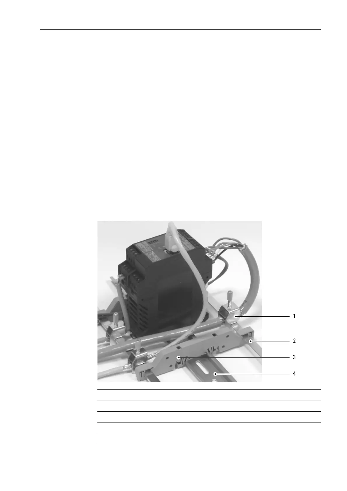
No. Description
1 Screen clamp (e.g. Phoenix SK8-D)
2 Screen rail (e.g. Phoenix NLS-CU 3/10)
3 Rail connector bracket (e.g. Phoenix AB-SK 65D)
4 Mounting rail (35 mm)
4 Device installation Transmitter Series PR 5220
EN-25 Minebea Intec

 Loading...