EasyManua.ls Logo

Mitsubishi L02CPU User Manual

Mitsubishi L02CPU
340 pages
To Next Page IconTo Next Page
To Previous Page IconTo Previous Page
Page #125 background imageLoading...
Page #125 background image
123
CHAPTER 3 CPU MODULE FUNCTIONS
3
3.19 Executional Conditioned Device Test
When setting a word device with a different data type, a device is regarded as the same device.
When a word device is set in the order of "D100 (16-bit integer)" and then "D100 (Real number (single precision))",
"D100 (Real number (single precision))" is registered.
When setting a device with a different modification method (such as a bit-specified word device, digit-specified bit device,
or index-modified device), a device is regarded as a different device.
When a word device is set in the order of "D100.F" and then "D100Z0 (Real number (single precision)), both devices
are registered.
(b) Registration from multiple programming tools
The executional conditioned test setting can be registered to a CPU module from multiple programming tools.
Note, however, that if an executional conditioned device test setting is registered with the same device name in
the same step, the existing data are overwritten.
Before registering executional conditioned test settings from multiple programming tools, click the
button to update the registered data.
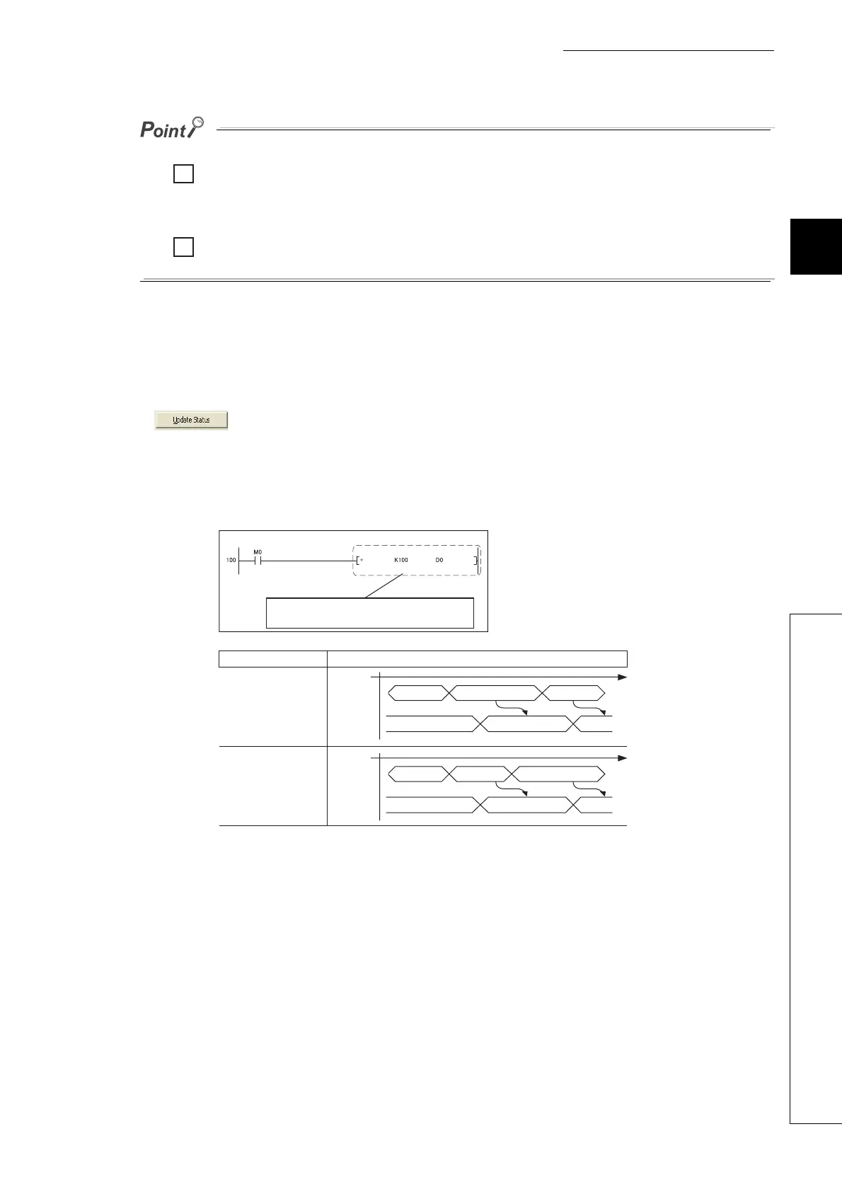
(c) Operation by different execution timing
Operation of the CPU module varies depending on the timing (either before or after an instruction of the
specified step) of changing a device value.
Note that, when registering the executional conditioned device test with particular instruction specified, a
device value may not be changed depending on the execution timing even after the specified step is executed.
The following instructions need to be noted.
Ex.
Ex.
Ex.
Ex.
[Program example]
[Operation]
Execution timing CPU module operation
Before executing an
instruction in step 101
After executing an
instruction in step 101
Processing
LD M0
10 20 120
Changes the D0 value to "20".
+ K100 D0
D0 value
Processing
LD M0
10 110 20
Changes the D0 value to "20".
+ K100 D0
D0 value
Register executional conditioned device test
that sets "20" to D0 in this step.

Table of Contents

Question and Answer IconNeed help?

Do you have a question about the Mitsubishi L02CPU and is the answer not in the manual?

Mitsubishi L02CPU Specifications

General IconGeneral
BrandMitsubishi
ModelL02CPU
CategoryController
LanguageEnglish

Summary

MITSUBISHI MELSEC-L CPU Module User's Manual

SAFETY PRECAUTIONS

Design Precautions

Essential safety guidelines for designing systems with the controller, covering circuits and operations.

Installation Precautions

Crucial steps for safely installing the programmable controller modules, including environment and interconnection.

Wiring Precautions

Important safety measures for correctly wiring the controller, covering grounding, terminals, and cable routing.

Startup and Maintenance Precautions

Precautions for safe startup, operation, and maintenance procedures, including handling batteries and static electricity.

PART 1 PROGRAMMING

CHAPTER 1 BASIC PROCEDURE FOR PROGRAMMING

Guides through the fundamental steps of PLC programming.

CHAPTER 1 BASIC PROCEDURE FOR PROGRAMMING

1.3 Creating a Program

Explains the fundamental steps and prerequisites for program creation.

1.5 Writing a Project to the CPU Module

Describes how to transfer the project, including memory formatting.

1.6 Checking an Operation of the CPU Module

Outlines procedures for verifying the CPU module's operation after programming.

CHAPTER 3 CPU MODULE FUNCTIONS

3.3 Watchdog Timer (WDT)

Details the watchdog timer for detecting hardware failures and program errors.

3.11 File Password 32

Explains how to protect files stored in the CPU module with passwords.

3.13 Remote Operation

Details methods for controlling CPU module operations remotely.

3.21 Writing Programs in RUN Status

Describes online program changes while the CPU module is running.

3.23 Self-Diagnostic Function

Covers the CPU module's self-diagnostic capabilities for error detection.

3.24 Error Clear

Explains how to clear detected continuation errors by type.

3.30 CPU Module Change Function with SD Memory Card

Explains data backup and restoration using an SD memory card for module replacement.

Appendix 1 Parameter Setting

Appendix 1.2 PLC Parameter

Details various PLC parameter settings including name, system, file, RAS, boot, and program.

Appendix 1.4 Remote Password setting

Provides screens and details for setting remote passwords for access control.

Appendix 1.2 PLC Parameter

2. PLC System Setting

Configures system-level parameters for CPU module operation.

4. PLC RAS Setting

Configures Reliability, Availability, and Serviceability (RAS) functions.

9. I/O Assignment Setting

Configures the connecting status and assignments of modules in the system.

Related product manuals