287
APPENDICES
APPEN
DIX
Appendix 1 Parameter Setting
Appendix 1.2 PLC Parameter
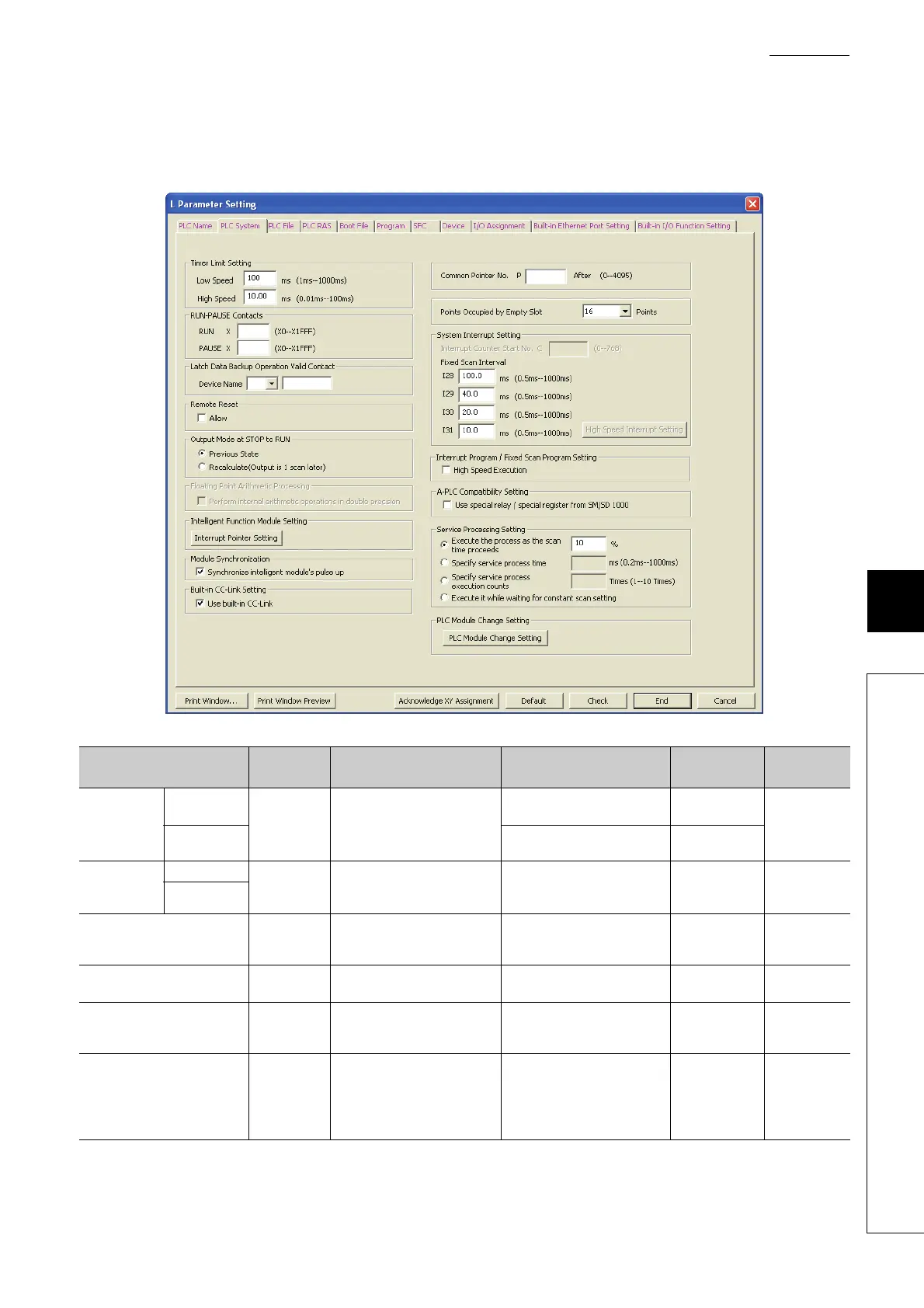
(2) PLC System Setting
Parameters of the system required for use of the CPU module are set.
(To the next page)
Item
Parameter
No.
Description Setting range Default Reference
Timer Limit
Setting
Low Speed
1000
H
Set the time limit for the low
speed timer or high speed timer.
1ms to 1000ms (in increments of
1ms)
100ms
Page 238,
Section 5.2.10
Low Speed
0.01ms to 100.0ms (in
increments of 0.01ms)
10ms
RUN-PAUSE
Contacts
RUN
1001
H
Set the contacts that control
RUN PAUSE of the CPU
module.
X0 to X1FFF ⎯
Page 106,
Section 3.13
PAUSE
*1
Latch Data Backup Operation
Valid Contact
1014
H
Set the valid contact device No.
used for backup of latch data to
the standard ROM.
X, M, B ⎯
Page 159,
Section 3.27
Remote Reset
1002
H
Select whether to allow the
remote reset.
Selected/deselected Deselected
Page 106,
Section 3.13
Output Mode at STOP to RUN
1003
H
Set the status of the outputs (Y)
when the operating status is
switched from STOP to RUN.
Previous state, Recalculate
(output is 1 scan later)
The previous
state
Page 93,
Section 3.7
Intelligent Function Module
Setting (Interrupt Pointer
Setting)
100A
H
Assign the interrupt pointers (I50
to I255) and set the start I/O
number and start SI number of
each intelligent function module.
• Start I/O No.
• L02CPU: 0 to 3D0
• L26CPU-BT: 0 to FF0
•Start SI No.
50 to 255
⎯
Page 273,
Section 5.10
 Loading...