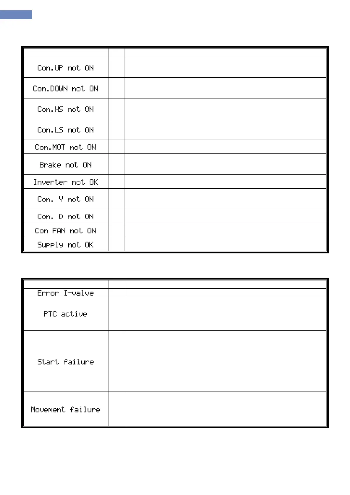
Messages that describe the contactor activation failure in the control group:
Indicates a direction up contactor activation fault. Contactor is controled by
defined input FI-220. Contactor must be on 2 seconds after system turns on
the output function FO-001.
Indicates a direction down contactor activation fault. Contactor is controled
by defined input FI-221. Contactor must be on 2 seconds after system turns
on the output function FO-002.
Indicates a high speed contactor activation fault. Contactor is controled by
defined input FI-223. Contactor must be on 2 seconds after system turns on
the output function FO-004.
Indicates a low speed contactor activation fault. Contactor is controled by
defined input FI-222. Contactor must be on 2 seconds after system turns on
the output function FO-003.
Indicates motor contactors activation fault, used with frequency regulated
elevators . Contactors are controled by defined input FI-225.
Indicates a failure to activate electromechanical elevator brake. Brake
control is done over brake contact at the input FI-224. Signal must be present
while traveling, and max 2 seconds after direction contactors activation.
Indicates a frequency regulator fault. Controled by input FI-226. Regularity
signal must be present all time.
Indicates a „star“ contactor activation fault used with hydraulic elevators.
Contactor is controled by defined input FI-227. Contactor must be on 2
seconds after sytem turns on the output function FO-013.
Indicates a „delta“ contactor activation fault used with hydraulic elevators.
Contactor is controled by defined input FI-228
Indicates a motor fan contactor fault. Contactor is controled by defined input
FI-209. Contactor must be on after system turns on output function FO-018.
Indicates a phase presence and sequence control relay fault. Relay is
controled by input FI-204.
Table with warnings and other failures:
Indicates that Bucher I-Valve don’t give output and it’s in error FI-313.
Indicates that the resistance of PTC sensor is above limit set by parameter
I-02 (hot state PTC resistance). Error remains on for another five min after
the signal, or once the probe resistnace falls below the value set by
parameter I-01 (cold state PTC resistance). Current PTC resistance can be
monitored in the menu inputs/outputs.
Indicates that the elevator after establishment of control signals from the
control group was not initiated in time set by parameter I-03. As a start
control, group takes into account all the signals except for a pulses for
copying used in copiying type 4 or 5 E-01. Parameter should be set to a
sufficient value needed to elevator pass the path between the 2 copiyng
signals when traveling at low speed increased by approximately 20%. After
activating the error it is necessary to reset the control disconnecting power
supply or using the reset button on LC100-D terminal. Inspection travel is
possible.
Indicates that the elevator after start from the station has not moved for
logner that the time set by parameter I-03. This message is identical to the
protection Start failure with the difference that after the start at least one
copying signal has changed . It is necessary to reset the control
disconnecting power supply or using the reset button on LC100-D terminal.