T200 User's Manual SECTION 3: WIRING AND INSTALLATION
PAGE 3-70
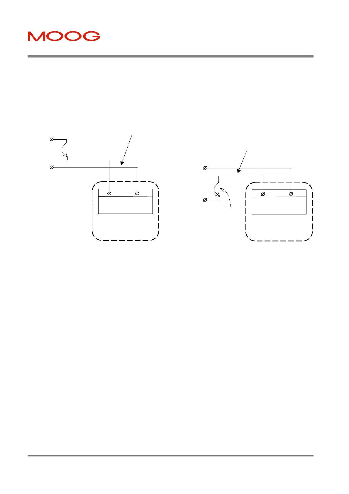
§ Figure 3.40 shows options for connection in pull-up or pull-down mode. Note that all inputs must be used in the
same mode for each T200.
§ Current flowing in the digital input implies the 'safer' of the corresponding active/inactive functions. For
example, when current flows in the clockwise limit switch input, then the limit is NOT active. See Table 3.9.
4
Digital Input I_COMMON
Connector J1
T200-XX0
26AWG (0.15mm
) Wiring
User-PSU
User's pull-down output
4
Digital Input I_COMMON
Connector J1
T200-XX0
26AWG (0.15mm
) Wiring
User-PSU
24V+
24V-
User's pull-up output
OR
Figure 3.40:- T200 Pull-Up or Pull-Down Options for Digital Inputs on J1
Artisan Technology Group - Quality Instrumentation ... Guaranteed | (888) 88-SOURCE | www.artisantg.com