Maintenance
6-10 October 2019 16K PLUS
Air Brake Maintenance - Continued
Adjust the brakes as follows:
1. Rotate the hex extension clockwise until the brake
linings contact the brake drum. Back off the slack
adjuster by rotating the hex counterclockwise 1/2
turn.
2. Backing off the slack will require approximately 25
to 30 ft lbs of torque. When backing off the slack
adjuster, a ratcheting sound will be heard.
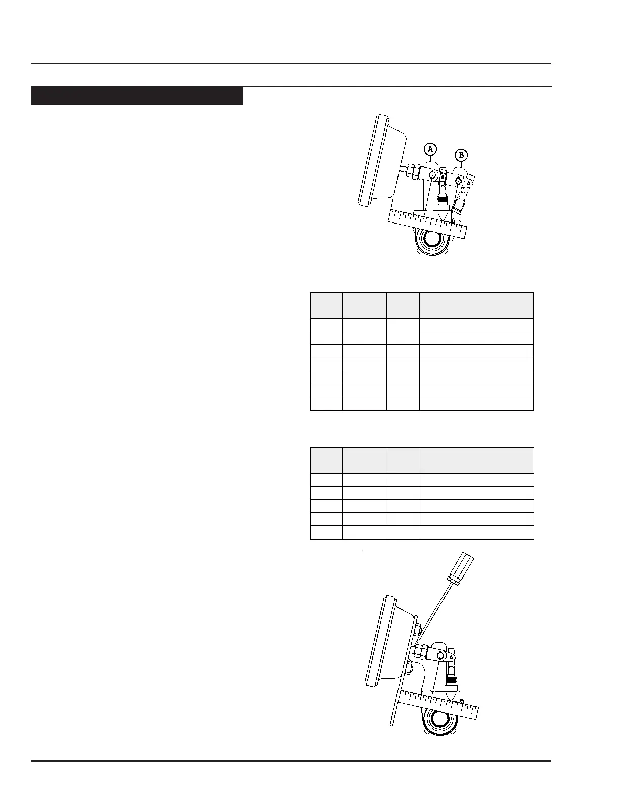
3. Using a ruler, measure the distance from the face
of the air chamber to the center of the large pin
in the clevis (A) (see g. 3). Make an 85 psi brake
application and allow the chamber push rod to travel
its maximum stroke. Measure to the center of the
large pin (B). The difference between (A) and (B)
is the push rod stroke. Check the following chart
for proper maximum stroke after adjustment of the
brakes.
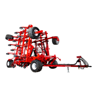
Measuring the Free Stroke
4. Free stroke is the amount of movement of the slack
adjuster required to move the brake shoes against
the drum. With brakes released, measure from the
face of the chamber to the center of the clevis pin.
Use a ruler to measure the movement of the slack
adjuster until the brake shoes contact the drum (g.
4). The difference between the released and applied
measurements is the free stroke. The free stroke
should be 3/8” to 5/8”. If the free stroke is good, but
the applied stroke is too long, there is a problem with
the foundation brake. Check the foundation brake for
missing or worn components, cracked brake drums,
or improper lining to drum contact. If the free stroke
is greater than the recommended distance (3/8” to
5/8”), a function test of the slack adjuster should be
performed (see page 6-11). If the free stroke is less
than 3/8”, a dragging brake can occur. Check to see
that the manual adjustment procedure was followed
correctly. Manually readjust the brake following the
procedure on this page.
Figure 3 - Measuring Maximum Stroke
Outside
Rated Maximum stroke at which
Type Diameter
Stroke brakes must be readjusted
9 5-1/ 4 1.7 5 1-3/8
12 5-1 1/1 6 1.7 5 1-3/8
16 6-3/8 2.2 5 1-3/ 4
20 6-2 5/3 2 2.2 5 1-3/ 4
24 7- 7/ 32 2.2 5 1-3/ 4
30 8-3/3 2 2.5 0 2
36 *93.00 2-1/ 4
Outside
Rated Maximum stroke at which
Type Diameter
Stroke brakes must be readjusted
16 6-3/8 2.5 0 2
20 6-2 5/3 2 2.5 0 2
24 7-7/ 32 2.5 0 2
24 *7-7/3 2 3.00 2-1/2
30 * 8-3/3 2 3.00 2-1/2
*Note: If type 36 chamber is used, slack length should be less than 6”.
*Note: Identified by square air port bosses.
“LONG STROKE” CLAMP TYPE BRAKE CHAMBER DATA
“STANDARD” CLAMP TYPE BRAKE CHAMBER DATA