Operation
16K PLUS October 2019 5-13
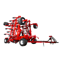
Power Slider Chain Tension
Setting Alignment Arm Pressure
• When the stacker picks up a bale in automatic mode, the arms will squeeze until the hydraulic pressure in the
cylinder exceeds the set-point. The arms then stop squeezing, and the loader starts raising. There are two
pressure set-points for the stacker. The 1st Bale Pressure is used for the rst bale picked up, and the 2nd Bale
Pressure is used for the next one. In the case of 3 X 3 bales, the 2nd Bale Pressure is also used for the third bale.
If the alignment arms don’t appear to be squeezing the bales tight enough or the bales are slipping through the
alignment arms, the pressure probably needs to be increased. If the alignment arms appear to be squeezing the
bales too tight and the bales are bowing in the middle, the pressure probably needs to be decreased.
• The Alignment Arm Pressure can be adjusted from the Adjust menu. See Adjust Menu: Example: Changing
the Squeeze Pressures for details.
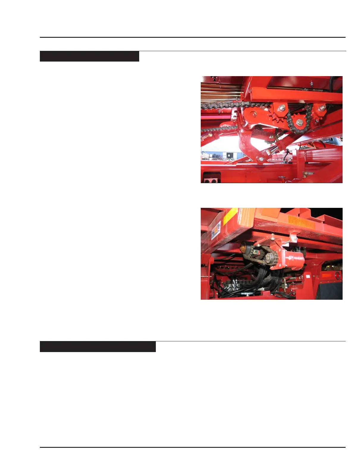
Chain Tension Adjustments
Warning: When making adjustments on the Bale
Runner, always stop the towing vehicle, set the parking
break, disengage the PTO and all power drives, shut off
the engine and remove the ignition keys.
• If the power slider chains are jumping teeth or appear
to be over tightened, then the power slider chain
tension may need to be adjusted.
• The Power Slider Chain Tension is controlled by a
hydraulic pressure reducing and relief valve located
on the side of the pushoff. The aluminum valve has
an adjustment screw protruding from the rear of
the valve. Once the 9/16” jam nut is loosened, the
adjustment screw can be turned with a 5/32” Allen
wrench. When adjusting the system use small
increments (1/4 turn), bottoming out the adjustment
nipple or over pressurizing the system could
potentially damage hydraulic components. Turning
the adjustment screw in (clockwise) increases
pressure, and turning the screw out (counter
clockwise) decreases the pressure.
• Adjusting the Motor Chain Tension can be
accomplished with two 3/4” wrenches. First
loosen the four (4) bolts holding the motor mount
to the bed. Then adjust the threaded rod until the
appropriate amount of tension is achieved in the
chain. (Approximately 3/4”of slack in the middle of
the slack side of the chain.) Re-tighten all bolts and
torque to specs. (Page 6-20)
Motor Chain Tension