5-24 Manual # 42-02-2223
System Options
Mechanical Configuration
• Ethernet Port: Standard Ethernet port. Used to connect this assembly to the System
Ethernet hub/switch using an orange Ethernet cable.
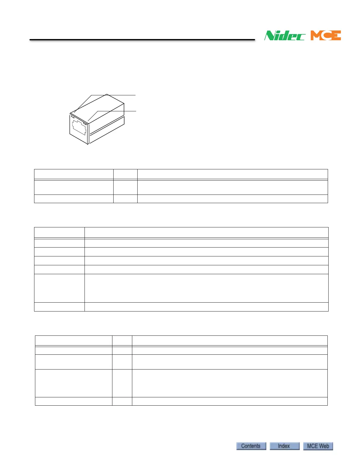
Figure 5.11 Ethernet Ports
Table 5.2 Ethernet Port LEDs
LED Color Description
Link Status/Integrity yellow Network link is operational: On continuously indicates that an Ether-
net connection is made.
Network Activity/Diagnostic orange Network Activity: Blinks when network traffic detected.
Table 5.3 SC-HCE-2 Indicators
Indicator Description
Bus Error ON = Communication problem. Blinking Rapidly = Bootloader running.
DS3 ON = Isolated CAN power supply OK
Link Status Yellow indicator, ON = Network link is operational. (located on the ethernet connector)
Network Activity Orange indicator, Blinks = Network traffic detected. (located on the ethernet connector)
ON ON = Board processor operating. Blinking Rapidly = another board at same address.
When board is first powered up or reset, this LED blinks the first digit, second digit, and
third digit of the software version number with a very short blink between each group for
separation.
V OK ON = Power to the board OK.
Table 5.4 SC-HCE-ME Indicators
LED Color Description
Bus Error ON = Communication problem. Blinking Rapidly = Bootloader running.
Link Status/Integrity yellow Network link is operational: On continuously indicates that an Ethernet
connection is made or an access point is engaged.
Network Activity/Diagnostic green Network Activity: On when network traffic detected; off when no traffic
detected.
Diagnostic: Flashes three times in even duration during power up or
reset, indicating successful startup.
FHCE OK ON = Power to the board OK.
Network activity
Link status